|
|
|
Jensen Monday Club |
|
|
|
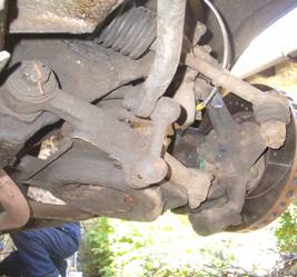
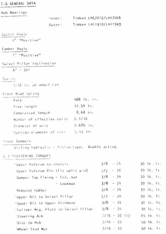
The purpose of this project was to: · Replace the front suspension bushes, because the originals were a mess. · To replace the Mk 3 front “road springs” with shorter Mk 2 ones, because this is how it should have been if it hadn’t been for US headlight height regulations. . Both sides of the front suspension were completed in one day and this also included messing about with the air conditioning, bleeding brakes, a lost dog and eating bacon butties. But there were three of us, two of whom had done this before. There won’t be mention anywhere about removing the wheels, jacking, axle stands, level ground, blah, blah, blah. All that safety stuff is left to the reader, and no responsibility, liability, blah, blah is accepted, in other words, if you mess up it’s not our fault… Figure 11 is a scan of the exploded view diagram from section “C” of the “Jensen Parts Catalogue (Interceptor III & SP)”. Figures 12a & 12b are scans of: “Section C.6 General Data” from the “Workshop Manual Jensen Interceptor II, III & SP FF II & III”. This gives the technical info such as tightening torques. The bushes used are “SuperFlex” polyurethane; you can visit the SuperFlex website at: www.superflex.co.uk and download an order form. The part number for a top wishbone bush is: SPF1199 (Jensen CT3423), you’ll need 4 of these at £5.75 ea. The bottom bush is SPF0286 (Jensen CT3443), also 4 needed at £9.95 ea. The second-hand “Spring – Front Coil” came from Rejen, about £50 the pair. Received wisdom is to do one side first then the other – that way you’ll have a reference if you get things out of place. There are various shims in the front suspension. Only those that affect the “Camber Angle” are removed during this procedure. This article does NOT explain how these work or how to adjust them, as this is covered very well in the workshop manual. The important thing is to note their relative positions and replace them as found, unless you know you already had a camber problem anyway. Three of the “Packing Pieces” can be re-positioned without undoing everything (just loosening) but the “Distance Piece – Joint to Link” can only be re-positioned with some disassembly so at least get that back where it came from (i.e. front or rear of the upper ball-joint assembly. Symmetry between the LHS and RHS is good, but if there’s significant wear on one side then the “Packing Pieces” may not necessarily be in the same positions on both sides, but usually are. The basic steps to replacement of the springs and bushes are: 1. Removal of the “Shock Absorber – Front”. 2. Removal of both “Arm – Upper Wishbone Assembly” , bush replacement re-fit. 3. Split the ball joint at the “Link – Anti Roll Bar” 4. Removal of the “Spring – Front Coil” and “Pan Front Spring Assembly” 5. Partial removal of the “Lower Wishbone Arm Assembly” , bush replacement and re-fit 6. Finally, in the words of the famously brief workshop manual “Refitting is the reverse of the removal procedure” The more detailed steps are: 1. Removal of the “Shock Absorber – Front”. Undo the top “Nut-lock” and “Nut” and then the four bolts at the bottom that holds the “Bracket – Mtg. – Shock Absorber” onto the “Pan – Front Spring Assembly” . The shock can then be withdrawn from below – retain the “Stem Bush” and associated washers (one each above and below the chassis mounting plate).
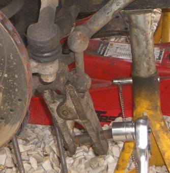
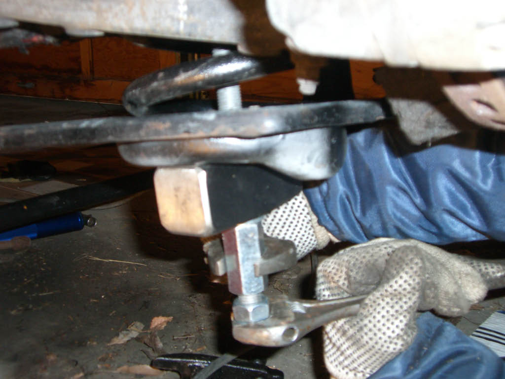
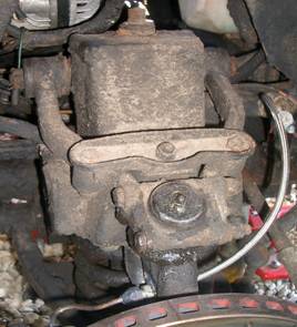
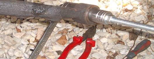
Figure 1: Four bolts removed from the bottom of “Bracket – Mounting. – Shock Absorber” 2. Splitting The Lower Anti-roll Bar Ball Joint. You need to separate the anti-roll bar from the spring pan. This can be done at the joint at either the top or bottom of the “Link Anti-roll Bar” . If you have a ball-joint splitter then the bottom one is the easiest to do (bloody difficult otherwise so you’ll have to undo the top of the link). If you’re replacing the “mounting Rubber Anti-roll Bar” now’s a good time whilst the main anti-roll bar is detached at one end.
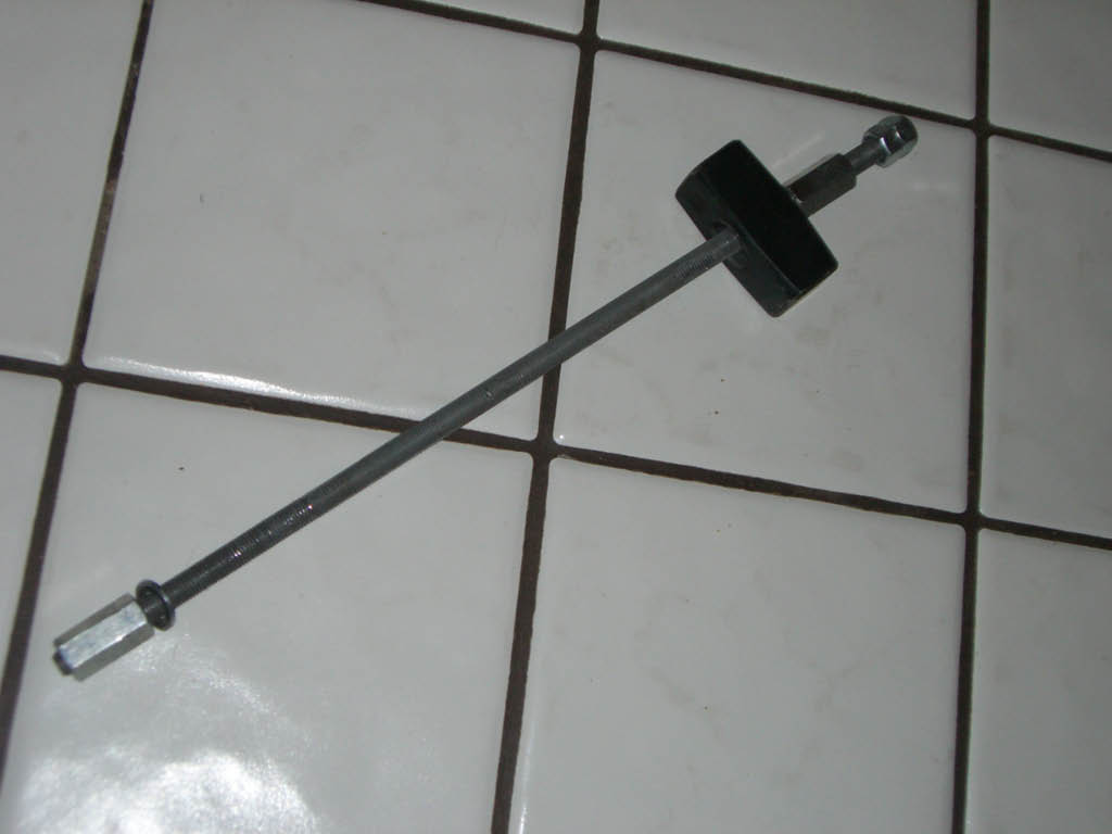
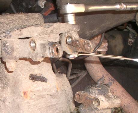
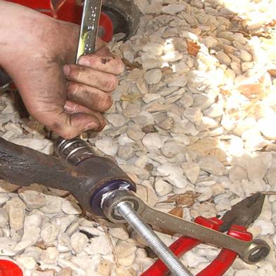
Figure 2: Ball-joint splitter tool (this ‘photo is of the other side) 3. Removal of the “Spring – Front Coil” . You can either use spring compressors (difficult and bit dangerous if they slip !) or Steve’s handy home-made “wind down” tool (very easy and safe). This tool is three threaded rods, a washer and a piece of tubing to make a sliding collar over the rod. Remove three of the six “Screws” from the under side of the “Pan – Front Spring Assembly” that holds the pan (and thus the spring under tension) to the lower wishbone arm.
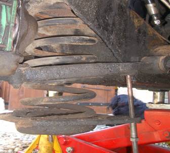
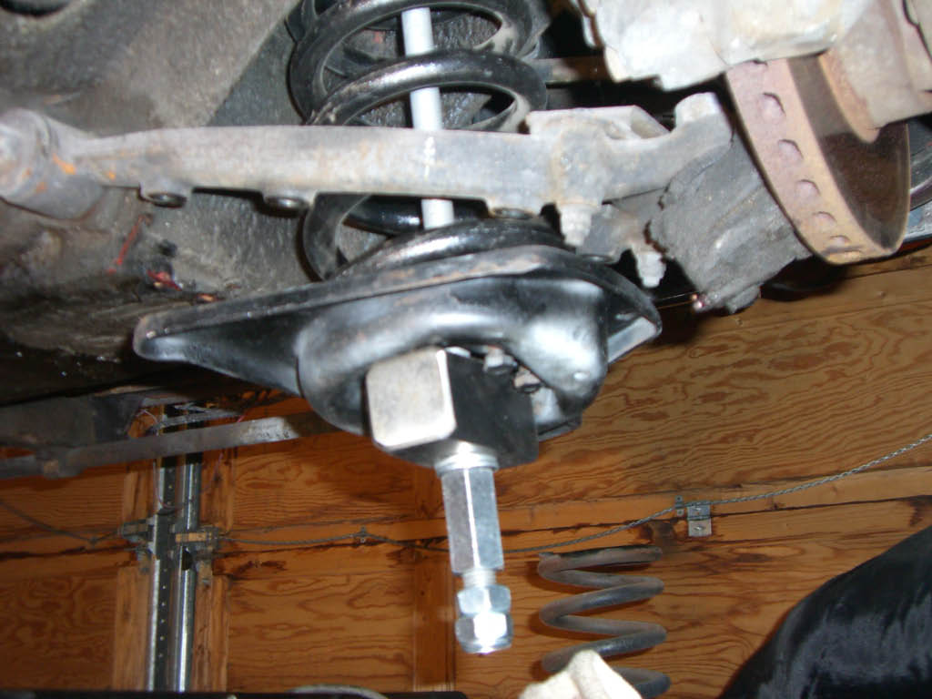
Figure 3: Two of the three “wind down” tools in place (the outside one was removed before this ‘photo was taken) Screw the rods into the pan, slide on a washer from below, then the collar, then another washer and then the nut. Wind the nuts on until the collars are touching the underside of the pan. Now release the three remaining “Screws” . The tension of the spring is now pressing down onto the three threaded rods. Wind the nuts down, evenly around the three rods; this lowers the pan and releases the tension in the spring. When all the tension is released (as per Figure 3) the three rods can be removed and the spring and pan removed. There’s an “Insulator Front Coil Spring” which will probably stay stuck up on the underside of the chassis. If not, just lift it out.
Petter Vennemoe sent us these photo's of his alternate spring removal tool as he was unable to find Imperial threaded rod in Norway. He removed the shock absorber and fitted a 16x650 threaded rod through the hole. He secured the rod at the top with washers and nuts, and then used the head of a small lump hammer underneath the spring base, secured with more washers and nuts. A good technique! Since publishing this article a JOC member used a single rod to remove a spring and it failed under tension. Luckily he was scared rather than injured, but if you do use a single rod ensure it is of sufficient strength to cope with the 488 pounds of spring pressure
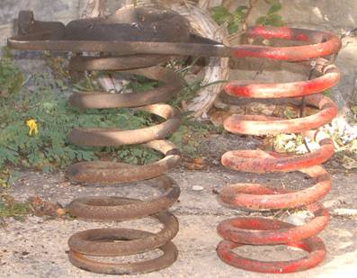
Figure 4: The original Mk III longer spring (black) and a shorter Mk II spring (red). The difference is about 1.5 inches (the difference is more noticeable when the pan is removed from the original). 4. Remove The Top Wishbone Arms. Undo and remove the two “Bolts Ball-joint To Upper Wishbone” bolts. These hold the upper ball-joint to the upper wishbones. This is where the camber adjustment shims and packing piece is – between the ball-joint and the wishbone arms.
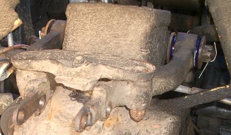
Figure 5: “Ball-joint Upper” in the foreground, “Bracket Mounting Rebound Rubber” behind. When the bolts are removed the whole suspension assembly will be able to fall to the ground so its weight needs to be supported (axle stands are ideal) as the bolts are withdrawn. Remember to note the positions of the one packing piece and the three shims. You only need to remove one of the retaining bolts between the rebound bracket and one of the upper wishbone arms. This allows the two arms to move independently of each other.
Figure 6: Bolts and Shims Removed; whole front suspension assembly lowered and supported. Undoing the “Bracket Mounting Rebound Rubber” to wishbone bolt. Next undo the two “Nuts Slotted ½” UNF” that hold the inside end of the upper wishbone arms onto the “Shaft Upper Fulcrum”. NB These nuts have split-pin retainers. You should now be able to remove the upper wishbone arms completely. 5. Replacing The Bushes Use a bench vice (or press) to push out the old bushes – they may even fall out if they’re anything like Kerry’s were… The simplest way is to use a large socket on one side and a socket just smaller than the external diameter of the old bush – you can then push the old one out.
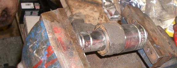
Figure 7: Pushing Out The Old Bushes; Steve’s hand and his tidy workbench! The new “cotton real” bushes are pushed in using the same method. Having two people doing this makes it much easier; one to tighten the vice and the other to “persuade” the new bush into the wishbone with a blunt screwdriver. Because the bush has a lip (i.e. like cotton real) it is difficult to get started but once pushed in will go in easily and its lip will “pop” out the other side. You need a big enough socket behind it to allow the lip to emerge without being squashed. If you don’t have a vice (other than spending money on your Jensen !), or a press you can use a threaded rod and a pair of nuts (see this technique in the next section). Final step before re-assembly is to press the steel sleeve into the centre of the new bush. Once the other wishbone has had its bush replaced it’s now a case of the dreaded “refitting is the reverse of the removal procedure”. Don’t forget the split pins in the fulcrum bolts. Here’s the new arm back in place. Note that rebound rubber mounting bracket to wishbone bolt has NOT yet been replaced – this makes pushing the shims into place a bit easier – but don’t forget to go back and do it at the end.
Figure 8: New Bush (see the clean shiny blue lips of the cotton reel bush); wishbones back in place. 6. The Lower Wishbones To detach the lower wishbones (at the inner end) remove the split-pin “Nuts Slotted 9/16” UNF” from either end of the “Shaft Lower Fulcrum” and pull the shaft out. You may need to drift it out; we tried Kerry’s thumb (loud but ineffective) and also an old nut reversed and hammered onto the end of the shaft (loud but effective). Best also to replace the nut to protect the shaft’s thread before hammering. The shaft only needs to be drifted far enough to get a proper grip on the other end; it can then be pulled through. If the shaft is bent (apparently a possibility after accidents) it may not come out in which case you’ll have to drift it one way to get one bush out and then back the other way for the other bush. You can replace the lower wishbone’s bushes with them still attached to the rest of the suspension assembly. Use a threaded rod a small and large socket and a couple of nuts (Kerry and Steve ideal) and press out the old bushes. The new bushes are like a cotton reel cut in half with a steel insert. Push one half of the bush in from each end and then press the steel sleeve through the middle of the bush; like so:
Figure 9: Pushing out the old lower bushes with a threaded rod, note the working surface below; ideal for “safe keeping” of any dropped nuts-washers.
Figure 10: Pushing the steel sleeve into the new bushes with threaded rod, nuts and sockets; and Kerry demonstrates the “reverse Australian spanner grip”. 7. Replacing The Road Springs & Shocks Just a simple reversal; lower fulcrum shaft and lower wishbone, then the springs, then shocks, then drive ! Here’s a list of the problems we encountered: · We had to hacksaw off the nut/locking nut on the top of one of the shocks. This damaged the thread such that a new bolt could not be fitted (the thread was very rusty and “gone” in places anyway). Two solutions were tried; grinding the flat top of the thread to a point so that a nut could be pushed further down to engage the thread – this didn’t work; and then cutting the damaged thread off at an angle which did, but with only just enough room for a nut and locking-nut. Plan B if there had only been enough thread left for one nut was either a nylon locking nut or drilling a hole for a pin/wire (glad we didn’t have to do that). · “Oh my god! We’ve finished but we’ve got all these parts left over”. The old bushes (both upper and lower) have “Prescollan” washers (big plastic looking) on either side. You don’t need these if you’re using the SuperFlex bushes which have a “lip” instead, but you do need to re-use the large steel washers. · When lowering the road spring pan using the three threaded rods if you don’t undo them a small equal amount each then the strain on one thread can cause it to strip or at least slip a bit – so do the unwinding at arms length. · It was hard work to separate the old road spring from its pan; it was rusted in pretty good. We should have “soaked and waited” but instead used the “fine adjustment tool”
which resulted in breaking off the small bracket that the bottom of the shock bolts onto. Luckily we had a spare pan, but unluckily there are two types; one with the anti-roll bar bracket pointing upwards and the other with it pointing down – you obviously need a matching pair. The problem was solved by epoxy resin bonding the old bracket back onto the old pan. This was ok because the bolt through it from the shock lower bracket pulls this joint closed not open. · When we removed the upper camber shims they were put somewhere “safe” – but we couldn’t remember where so spent half an hour “dismantling” (with an angle grinder) an old junk assembly to get the shims from that one. Of course as soon as we’d done all that the original shims were mysteriously “found”. I suspect it was Kerry’s dog telling us it was time to stop for bacon butties… · Kerry’s dog went “walkabout” (guilty conscience ?); but it didn’t take as long to find the dog as it did the shims… That's All Folks!
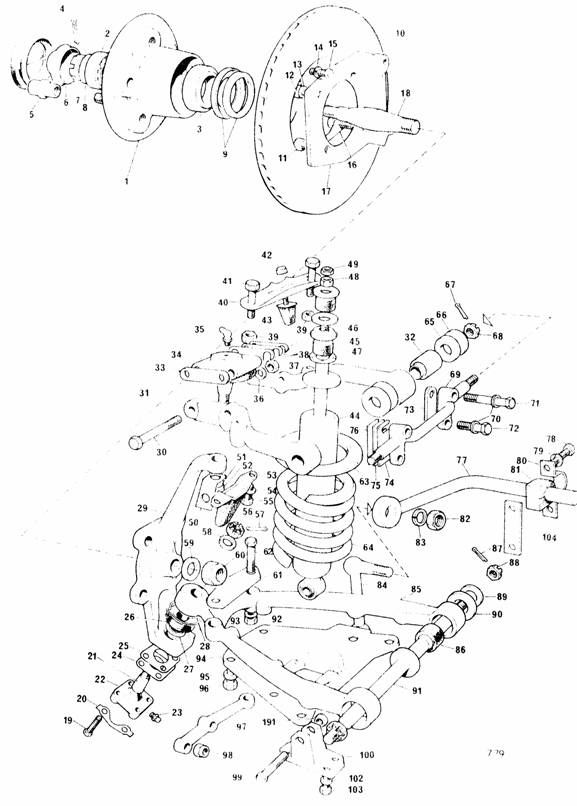
Figure 11: Exploded Parts Reference Diagram
|
|
|