|
|
|
|
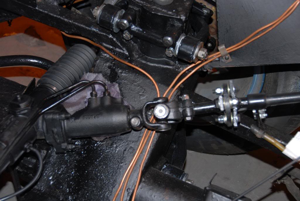
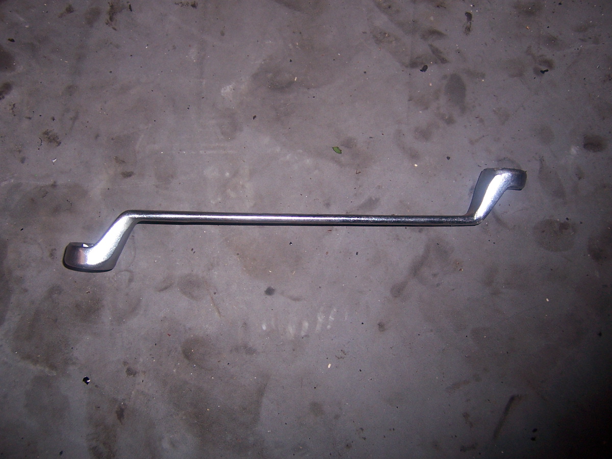
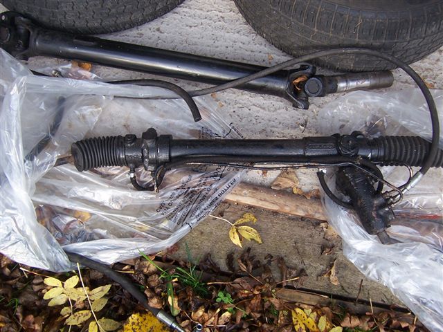
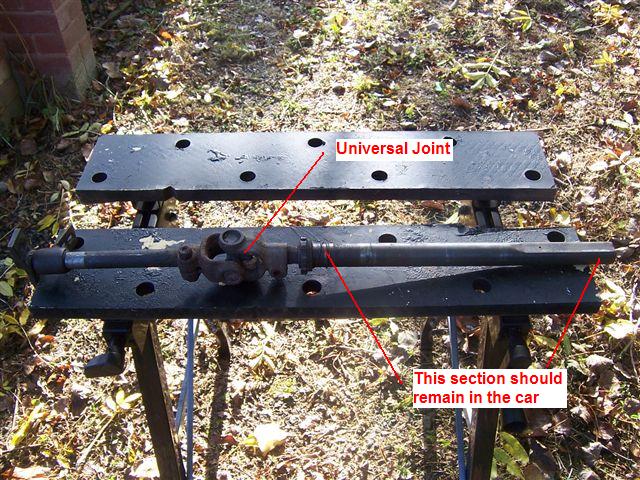
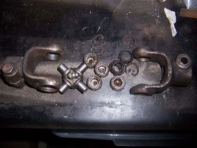
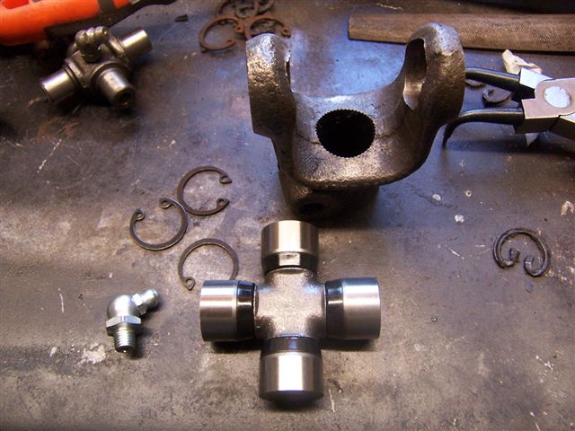
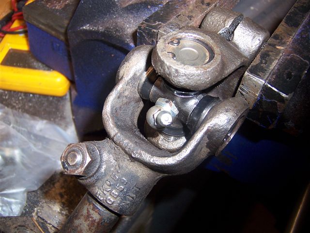
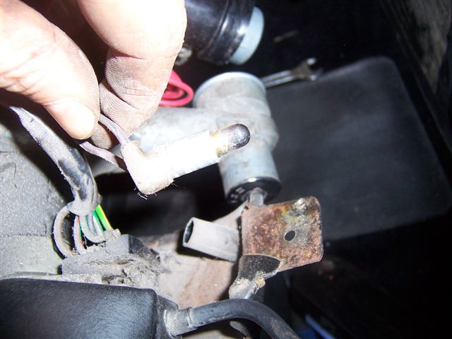
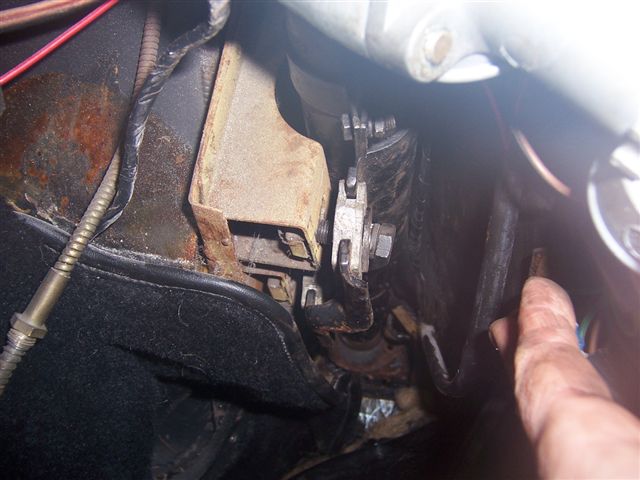
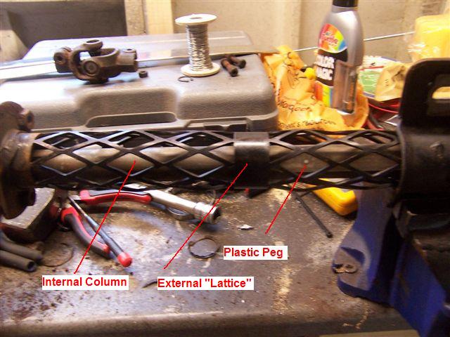
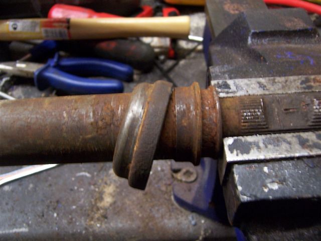
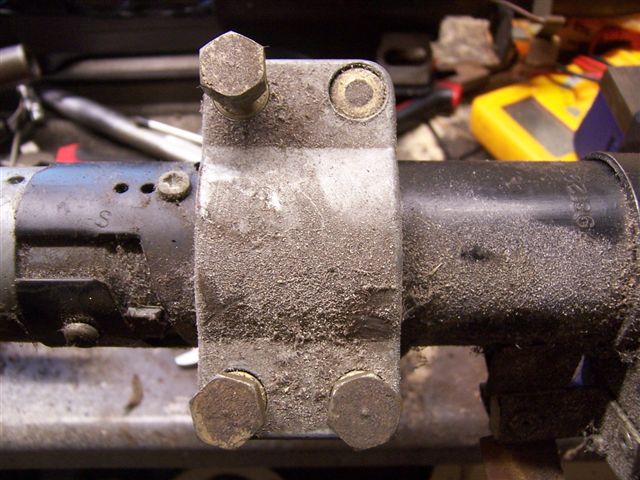
Steering racks. Comical, flightless, web footed little barstards. No wait. That's penguins. Steering racks. Started off as a nice straight forward job. The rack had always had play since I bought the car. At first I thought it was just the way it was as it was an old car, but after helping Steve Payne fit a new one to his car, I found out they were meant to be play free. Various MOT testers had mentioned that there was play. Not enough to fail the car, but they mentioned it. There was also about 1 inch of free play at the dead ahead position. Again, not enough to be a problem on most roads, but on the narrow country lanes where I live it was enough so you lost a bit of confidence at placing the car where you wanted it on the road. There was always something more important to do on the car previously, but as I had completed all the other jobs on my list, it was time to sort it out. Chris Miller had a refurbished rack knocking about, so he let me have that one so I didn't have to send mine away. A word to the wise! Jensen, Jaguar, and Aston Martin all used this rack. Jensen and Aston had different valve settings which made the steering a little heavier and more "feel-some". Jaguar used very light valve setting, which gave feather light steering, with less "feel" One rack refurbishment company sent Steve Payne a Jaguar spec rack by mistake, and Steve said it was like steering on ice. Make sure you specify the right rack if you use a non Jensen supplier. A second word to the wise! For some reason some of the refurbished racks won't fit the hole spacing on the Jensen chassis. Whether the Jag or Aston versions has very slightly different hole spacing's, or whether when the racks are stripped and rebuilt they are reassembled a thread longer or shorter I don't know, but about 1 in 3 will not fit. This means having to open up the holes in chassis to suit so check your old rack against the new to see if the holes match. Bizarrely, some times only 1 hole will be out... Here is an overview of the rack, U/J/s, and doughnut:
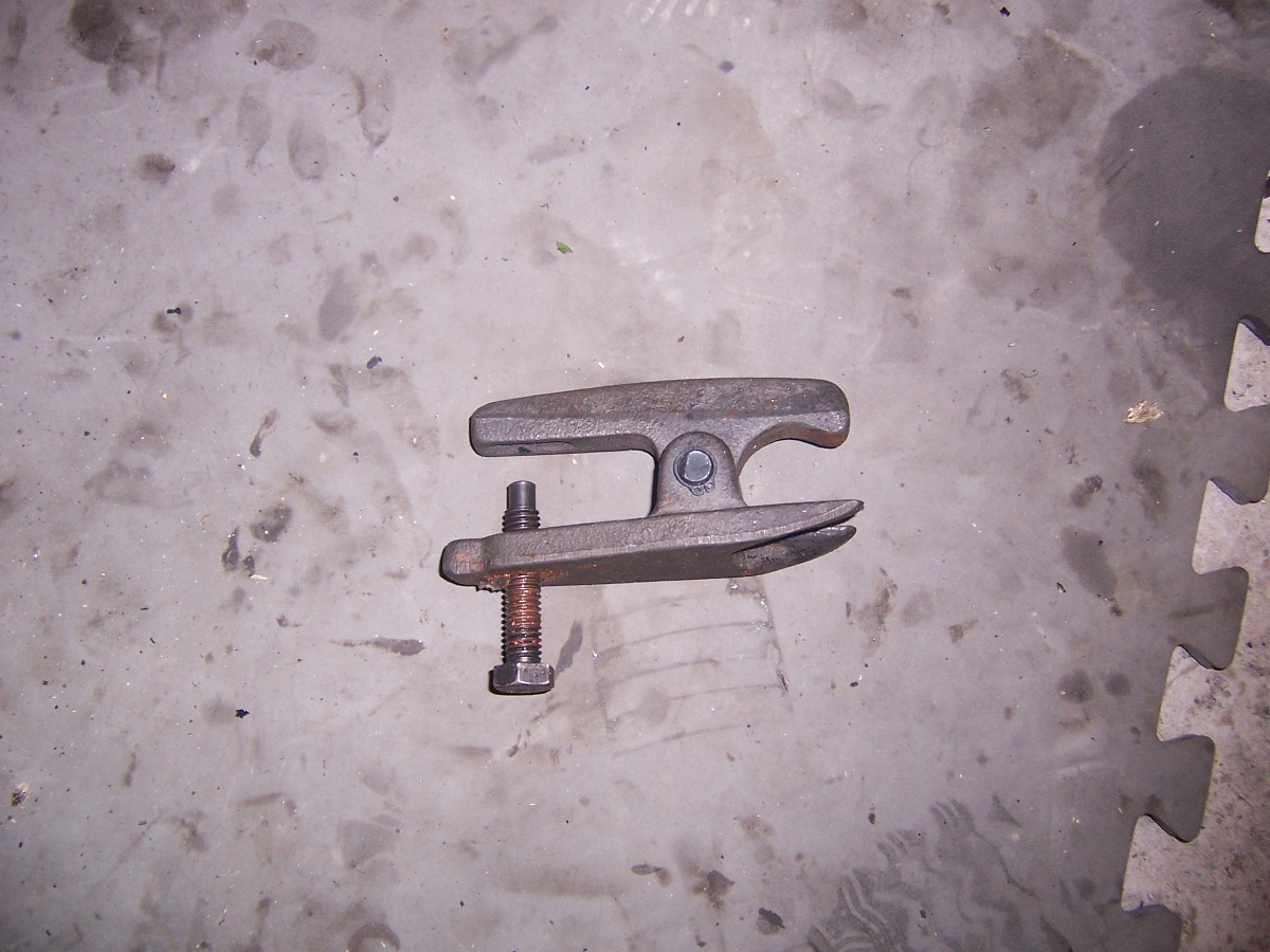
First job is to split the track rod ends. A proper splitter will prevent damage to the track rod, and make life a lot easier.
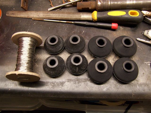
I bought a complete set of track rod and ball joint rubbers off E-Bay for £10. Search for "Jaguar Rod Boots". They come as a set of 8, so you can change all your rubber boots in one go if they are damaged. The annoying thing is they don't come with the spring locking rings (daft if you ask me), so I bought some stainless steel locking wire to do the job.
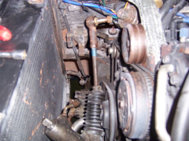
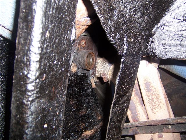
Next job is to undo the 4 bolts that hold the rack to the chassis. These are difficult to get at, and the only thing I could find to do it was a long swan neck ring spanner.
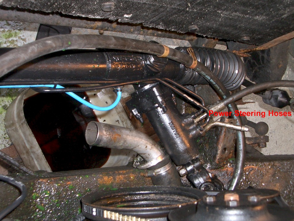
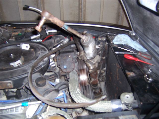
The last item holding it in are the flexible hydraulic pipes. Again difficult to get at as they are obscured by metal pipes on to of the rack.
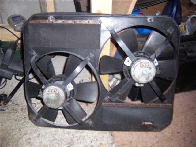
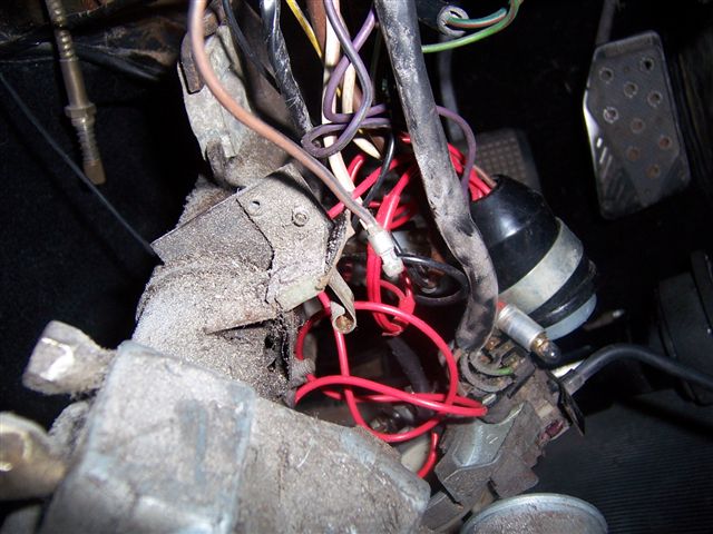
The picture above is from when we did Steve Payne's car, and we removed the radiator thinking it would be in the way. As we have since found out, removing the fan shroud will give enough room, and save the mess of draining the radiator
You can now slide the rack over to the passenger side, and get it under the passenger wheel arch. Move it over far enough to allow the drivers side track rod end to be lifted up in the engine bay.
Once the drivers side is clear in the engine bay, start and feed it in from the passenger side, and lift it out of the engine bay. It will be easier with 2 people, but I did this on my own.
New rack waiting to go in. If you are reusing the old pipes, or fitting new ones, do it now rather than try when it is back in the car...
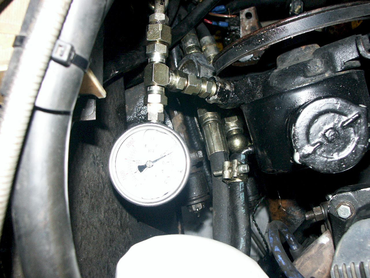
Refitting is the reverse of the above, but take care to make sure you really tighten the 4 bolts that hold the rack in as the rack take a lot a pressure steering such a heavy car. If your really bothered, so can fit a pressure gauge either permanently or temporarily to check you steering pump pressures. The pressure developed by the pump is dependant on the model and the year, and can vary from 1050 to 1550psi. It would be advisable to check in the workshop manual for your model of car.
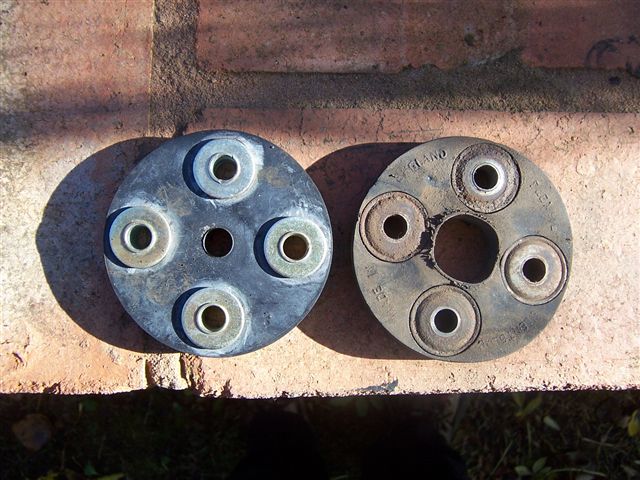
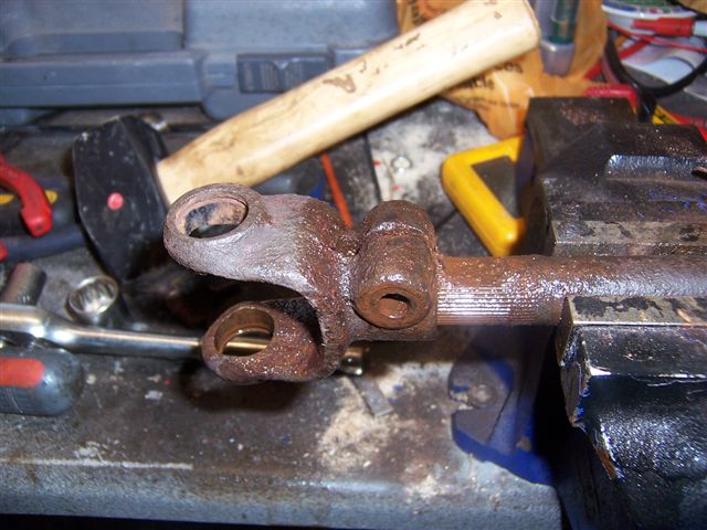
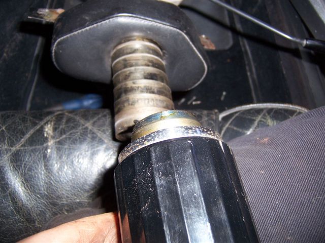
While I was taking it out I thought it a good time to overhaul the steering column at the same time. The column comes in 3 sections; there is one in the car, where there are really no user serviceable parts, and the 2 sections in the engine bay from the bulkhead to the rack. The sections in the engine bay comprise 2 shafts with a universal joint (U/J) at the end, and a rubber "doughnut" which joins the 2 shafts together.
The plan was to refurbish the 2 U/J's, and replace the rubber doughnut. This is where it all started to go horribly wrong... I undid the rubber doughnut (4 bolts) and removed the 2 bolts that hold a support arm. The 2 U/J's could now be removed from the steering rack and the steering column. The U/J on the rack came off easily enough (just 1 bolt secures it), but when I tried to remove the U/J from the steering column, instead of the U/J coming off, the whole of the column from inside the car came out instead!
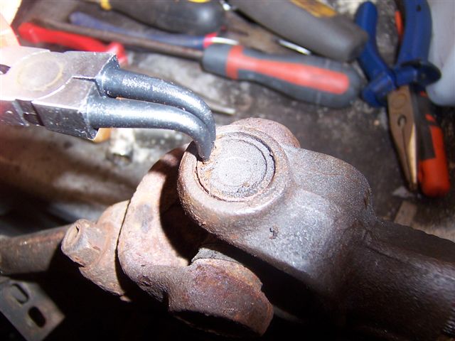
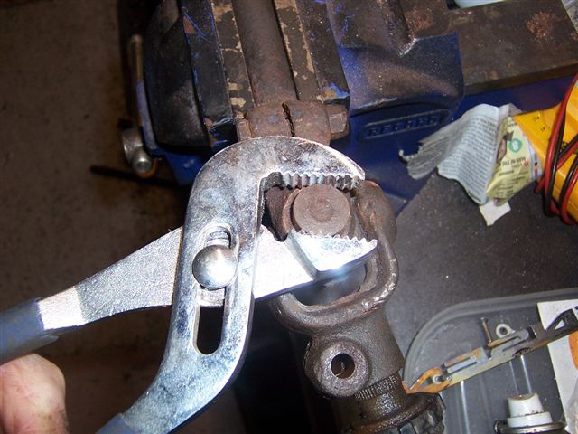
This meant a new internal column was required. Luckily we had one in our stock of spares, so a trip to Steve Payne's had one sorted. The next step was to refurbish the U/J's. I spoke to Andy Brookes of Appleyard's spares and he has new complete U/J's, and refurbishment kits available. When I asked which was best Andy told me the complete new ones are not as substantial as the originals, so I decided on the refurbishment kits. I started by removing the circlip's
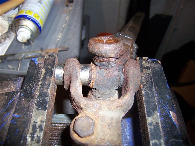
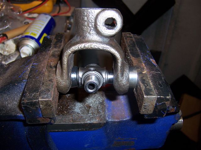
then pressing out the old U/J bearings in the vice using sockets.
The finish it off by using a socket larger than the bearing, so it can push inside.
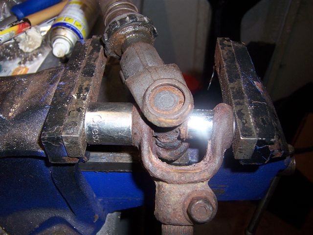
You can only press them out so far, then you have to use some grips to finish pulling the bearings out.
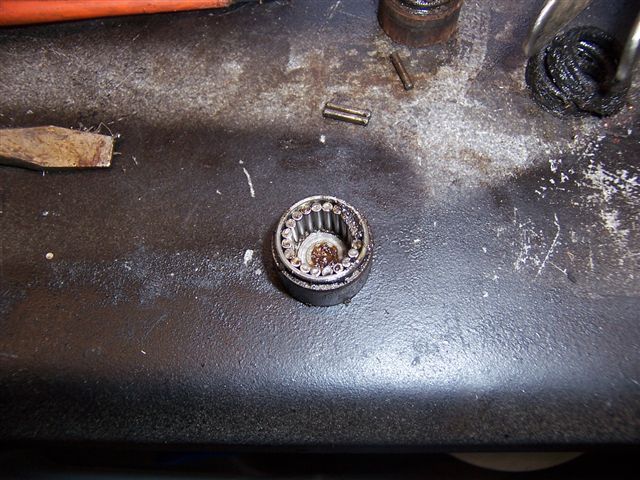
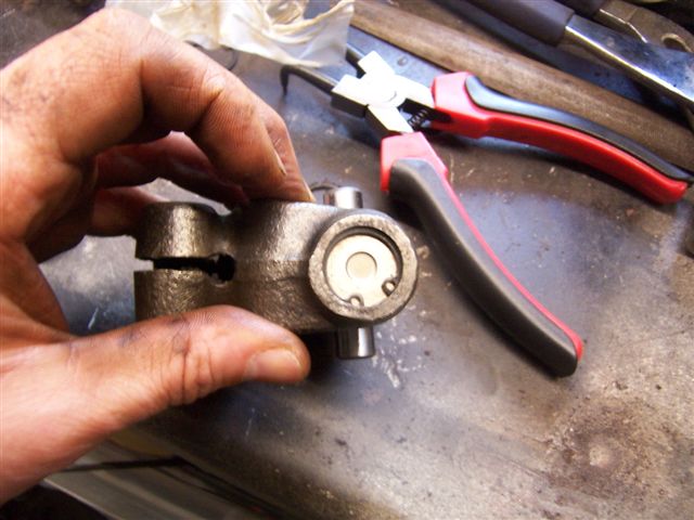
This is what the inside of the bearing looks like (there are 4 per U/J)
It turns out that the top U/J very rarely wears out as it is mounted in a straight line, but the bottom one onto the rack wears out quite badly as it is always turning at an angle. This was the case with mine where some very noticeable "flat spots" could be felt in the joint when I moved it around. The steering on my car would sometimes "stick" in some positions, so I think this may be the cause. Although the top U/J doesn't wear, it does get very hot from the exhaust manifold, and was very hard to get off the shaft due to the heat corroding it on. I had to use a lot of penetrating oil and a large "fine adjustment" tool.
Once they were disassembled, it was a case of cleaning the rust out of the holes with a round file, and clearing out the circlip holes with a small screwdriver. It was then ready for the new kit to be fitted.
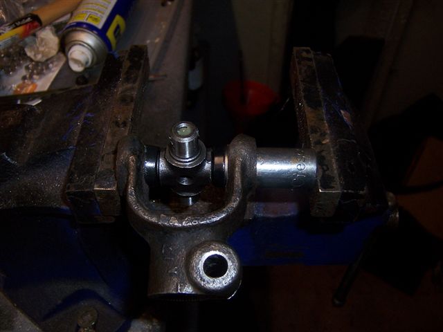
I fitted a new circlip to one side so I knew how far to press the bearing in.
The refitting is the reverse, but taking great care to keep dirt out of the new bearings, and to press them in square.
Make sure the grease nipple is fully screwed in so it doesn't catch on the joint, and that it is angled so you can get a grease gun on to it.
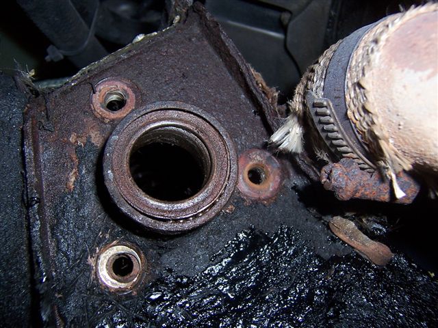
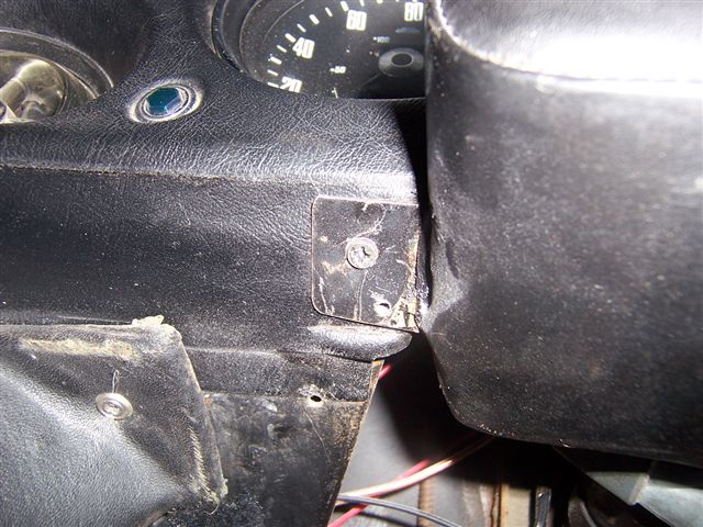
The next job is to remove the column section from inside the car. This is held in by 3 bolts near the ignition switch, and 3 bolts where it goes through the bulkhead.
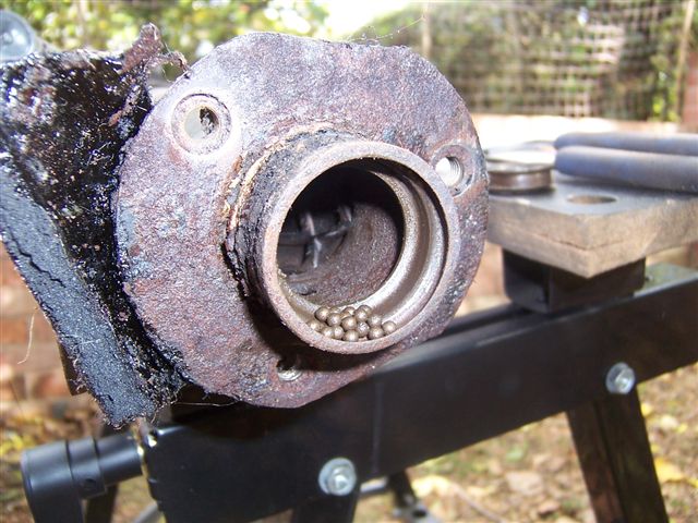
Close up of the bearing on the end of the column. This one has collapsed, and you can see the ball bearings at the bottom.
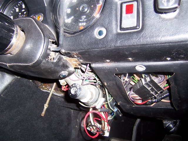
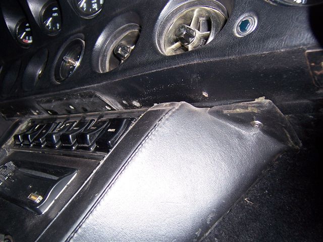
Once these 3 bolts were out, it was time to move into the car. You will need to remove the steering wheel, and some of the dash trim. The get the trim from around the indicator stalk you will need to remove the finishers from the bottom of the dash
This will allow you to access the screws which retain it.
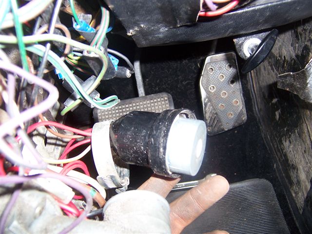
You can them remove the jubilee clip which holds the ignition switch in place.
And then remove the bulb holder from the ignition switch illumination light, and the wire from the indicators to the column.
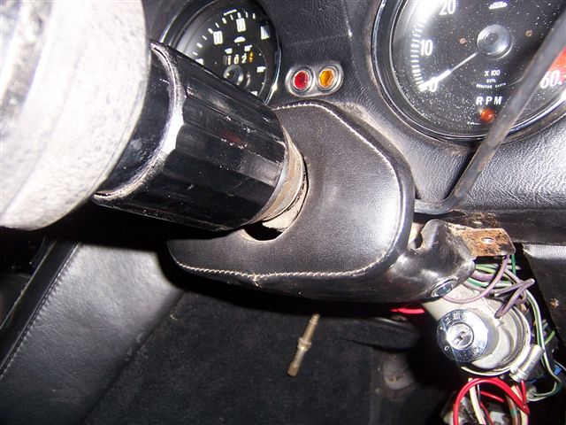
Once these are removed, undo the steering column reach adjuster, and remove it and the coil spring behind it.
You can now undo the screws which hold the indicator mechanism in place and remove the indicators
The 3 bolts which hold the column in place can now be removed.
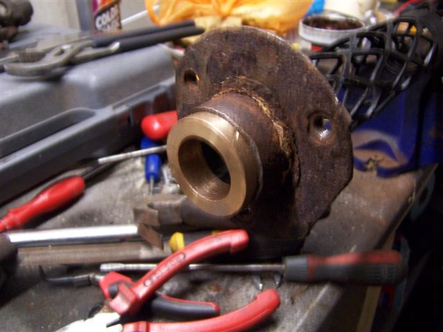
The column was then removed to reveal the collapsed bearing
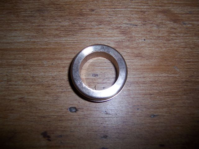
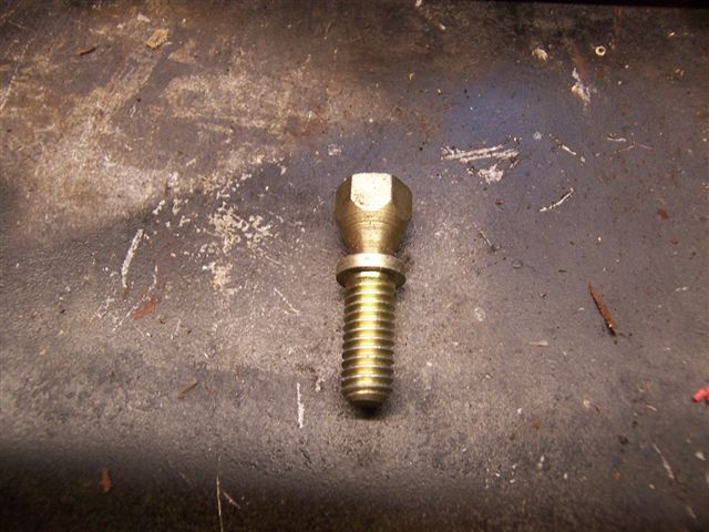
The spare steering column had a better bearing at the end in that it hadn't collapsed, but you could hear it was bone dry, and there was no real way of getting any grease into to it. What appears to be a large castellated metal nut holding the bearing in turns out to be plastic, and attempts to move it to get some grease into the bearing were abandoned as it was obvious it would break very easily. I called Andy Brookes who informed me the plastic castellated nut and the bearing were no longer available, but that he had got some phosphor bronze bushes made to replace the bearing, and that they wouldn't require greasing and would stand up to the heat from the exhausts. As I didn't want to be doing this all again when the replacement bearing finally failed at some time, I ordered the phosphor bronze bush from Andy. A couple of days later this little beauty arrived.
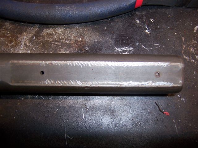
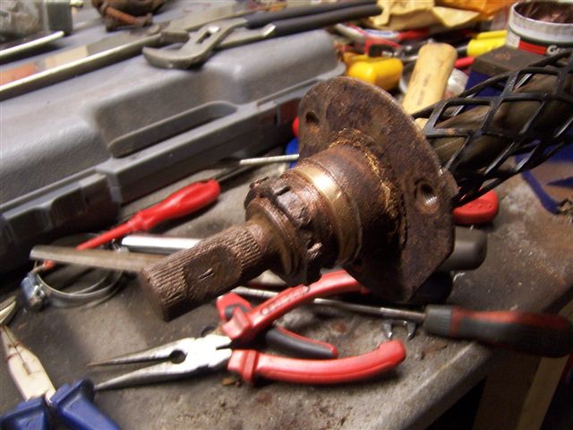
I couldn't understand why my column had come apart, but looking at the replacement, the internal column is in 2 pieces, in which one is a slide fit inside the other. They are then held together by plastic pegs. The idea of this is that the external column is made up of a "lattice", which collapses in a front impact rather than driving the column up into the driver.
During the lattice collapsing, the plastic pegs snap, and allow the 2 halves of the internal column to slide over each other, again stopping the column being driven into the car
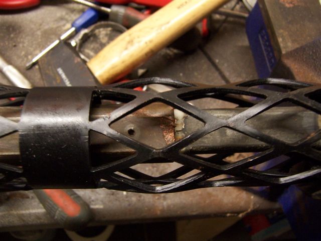
After checking with Andy Brookes, the only was to fit the new bronze bush is to take the 2 halves of the column apart, so I drilled out the plastic pegs. I thought they went all the way through like a dowel, but they don't.
I can't explain how it was made to be honest as inside the 2 halves of the column there are plastic "sleeves" and the pegs seem to come out of the sleeves, but I can't see how???
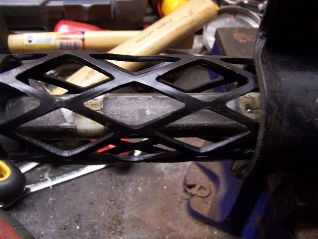
Once the 2 halves were apart, I removed the old bearing.
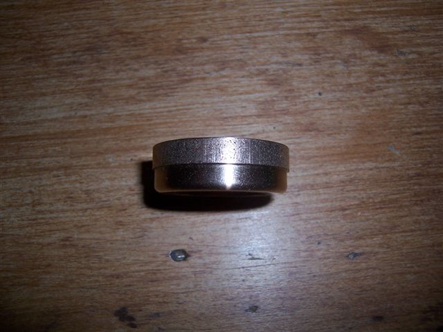
The bronze bush could then be re-fitted to the column.
And the shaft in inserted.
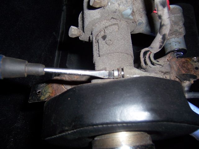
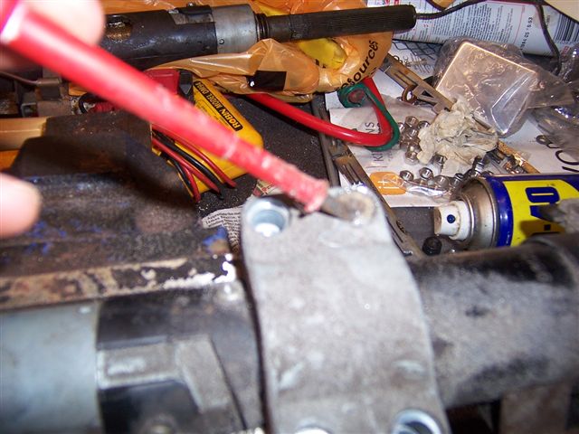
The next job was to take the steering lock off the old column and fit it to the new one. This can be difficult as there are bolts holding it on which are designed to sheer off when tightened to a certain torque, leaving a flush finish so thieves can't remove it.
Luckily only one of mine had been broken off
I used a screw driver to turn it gently.
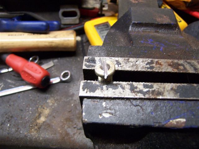
Once it was out I cut a slot in it with a hacksaw.
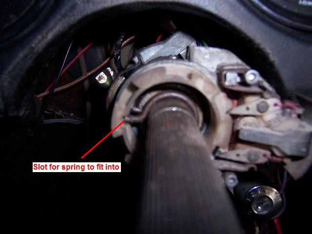
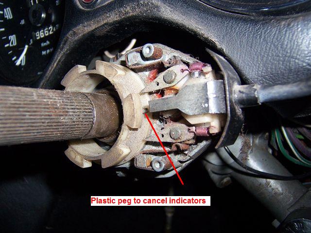
Once the column was back in the car and bolted back into place, the refitting of the indicators can take place. There is a plastic collar which operates the indicators which needs lining up. There is a spring clip which its around the column and fits into a slot on the plastic collar.
Once this is in place, you can then line the indicator mechanism up with a peg on the plastic collar.
It's just a case now of refitting everything, making sure you get your wheel in the dead ahead position so you can refit the steering wheel in a straight line. What started as a quick job rapidly turned into a major project, but it's done now and won't need doing for a veeeerrrry long time I hope.
|
|
|
|
|