|
|
|
Jensen Monday Club |
|
|
|
Spoiled by the luxury of remote central door locking on your modern car? Is going back to having to unlock the door yourself a real culture shock? Then read on and find out how to give your MK3 some mod cons. This article is about the installation of keyless remote central locking. At first this may sound like a complex job to do on a 30 year old car, but for a lees than princely sum, and about 2 hours work, the competent home mechanic-electrician can complete the job a lot easier than you might think. The job is made easier by the fact that the MK3 comes with central locking on the passenger door as standard. This means that almost half the wiring and parts are already fitted. All that remains for you to do is add the solenoids to the driver’s door (which do the locking) and a remote control unit. Parts RequiredAs Jensen already fitted central locking to the passenger door, you only need to add the mechanical locking equipment to the driver’s door. The whole package of solenoids, brackets, and rods can be ordered second hand from any of the Jensen parts dealers. I had mine from River Bourne, although by now they may be getting scarce. The next part you will require is a bracket to mount them on. The mounting brackets are not the same for the drivers and passenger doors, so you will need the bracket to suit. If you are fitting them to a right-hand drive UK driver’s door, you will need a bracket from a European or US passenger door, which is available from Martin Robey’s, part number #75376 If you are doing this on a left-hand drive European or US car, you will need a UK passenger door bracket, Robey’s part number #75377 (if you are ordering the solenoids from a UK supplier, you may find that the bracket that comes with them will be from a UK passenger door, so it will be the correct one for your driver’s door). Note! Mk3 owner, Dave Newby has done a similar conversion, but managed to turn the bracket upside down, and fit it that way! The remote control unit is available from EBay, Amazon, etc. There are plenty to choose from. The final parts you will require are 2 diodes capable of taking approximately 2 amps at 12V. You will need these if you wish to make the cars indicators flash when the unit is activated. These can also be ordered from Maplin, EBay, etc.. Fitting. As with any wiring job, disconnect the battery BEFORE you start, and make sure all your connections are correct and not liable to short circuit before you reconnect it. It is good practice to test all circuits before final connections are made. First remove the driver’s door card. This will require the removal of the chrome edging strips, the door handle, and the door-locking knob. As you remove the door card, carefully remove the wiring from the door-locking switch. The next step is to find a location to mount the control unit. Fortunately this is very small (about the same size a cigarette packet), and can be easily mounted, just ensuring the window lowering mechanism doesn’t catch on it.
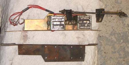
Picture 1: RHD Passenger Door Solenoids Transferred from Their Original Bracket (bottom) Onto a LHD Passenger Door Bracket (top). Once the unit is mounted, the bracket can be fixed. On my car, there were already holes for the bracket drilled in the doorframe, it was just a matter of drilling them out to suit the size of fixings to be used (don’t use fixings with to large a head, as you won’t be able to get the door card back on if they stick out to much). Once fixed, the rod from the solenoids can be attached to the door locking rod, ensuring this can slide side-to-side smoothly. WiringAfter fixing the control unit, and the solenoid brackets, the wiring can commence. The Interceptor wiring diagram is available form the Jensen Owners Club web site https://joc.org.uk/product-category/books-wire-diagrams/ and is essential at this point. There are 3 wires on the back of the door-locking switch. The brown wire is a permanent 12-volt live feed, which we will use to power the control unit. The other 2 wires are the solenoid wires for the passenger door. One is brown with a red stripe, which is the wire to the “locking” solenoid, and the other a brown with a green stripe, which is the wire “unlocking” solenoid.
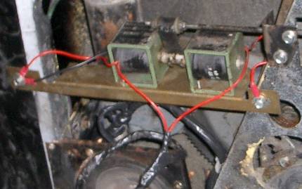
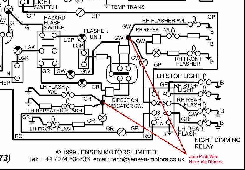
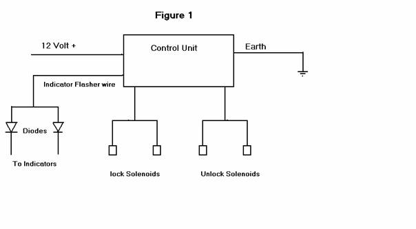
Picture 2: New RHD driver’s solenoids connected to the existing wiring leading to the RHD passenger’s door solenoids and remote control unit. These wires need to be connected to your new lock and unlock solenoids, so both doors work in unison. The control unit and the passenger and driver’s door solenoids now need to be connected up as per the wiring diagram in the control unit’s instruction book marked “Positive Pulse System” (See Figure 1) A final touch is to connect the pink wire from the control unit to the indicator wiring, to flash the indicators simultaneously to show the unit has activated. The wiring for the indictors can be found by the ignition switch, and should be connected via the diodes to the pink wire (you will need 2 IN5400 diodes, Maplin Part No QL81C). The diodes will prevent the indicators flashing simultaneously during normal operation.
All that is left to do now is to check the operation of the system, and adjust the new solenoids and rods to allow smooth operation of the door lock. As long as you have made sure that your connections are correct, and you have the correct brackets before you start, the job can be done in about 2 hours. Worried about reliability? Steve Payne has had this system on his car for 18 months, with faultless reliability. 21st century electronics on an Interceptor. Whatever next? Well, you can get optional extras for this central locking control unit, which includes a connection to close your electric windows when you lock the doors. Watch this space…
|
|
|