|
|
|
Jensen Monday Club |
|
|
|
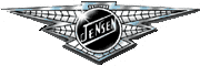
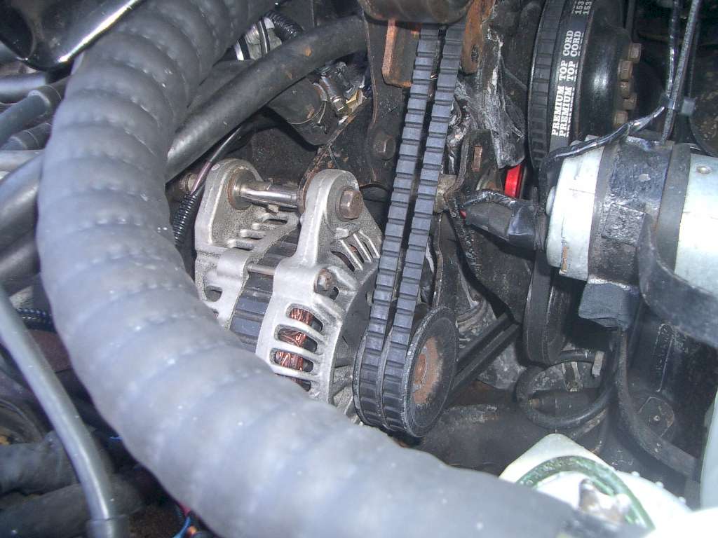
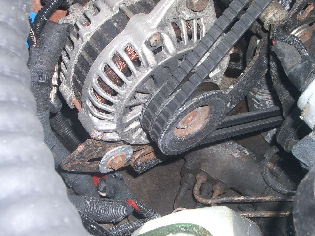
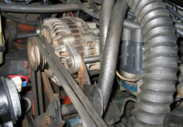
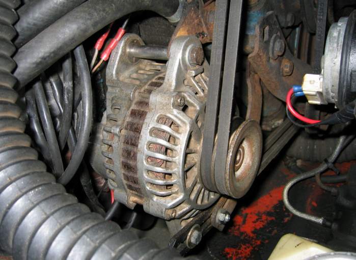
The Interceptor is as thirsty for electrical power as it is for fuel, and the standard Mopar 60amp alternator struggles to supply the power for fans, headlights, etc, especially at idle. There are many aftermarket alternators that offer huge current ratings, but they either tend to have very short life spans in the heat of the Interceptors engine bay, or are to big to fit in the space. Japanese cars have an enviable reputation for reliability, so the search was on to find a Japanese alternator that gave a good increase in current capacity over the standard alternator, but would fit in the tight space available. In the end, an alternator from a Mitsubishi Shogun 2.8 Turbo Diesel (1997 to 2000) was selected. Here is Chris Miller's story.
Finnish MK3 owner, Mark Lonngren, sent us these pictures below of his Mitsubishi alternator conversion. Mark is very pleased with the upgrade, having picked up his alternator form a wrecked 1999 Mitsubishi car.
Wiring There are three connections on the back of this "internally regulated three wire" alternator: 1) A big bolt with a plastic spacer and a washer-nut. This is the main power output and needs to be connected to a new heavy gauge cable (at least 100A and multi-strand flexible is good). The positioning of the connector is such that it will short out on the cylinder head unless you cut the end off the bolt to just leave the minimum necessary to hold the ring-end of the heavy duty cable plus one nyloc nut. You will also need to use an insulated boot on this connector, an old HT plug boot held in place with a tie-wrap works well. Even so this connector will be very close (about 3-5mm) to the cylinder head so always make sure the battery is disconnected when adjusting the position of the alternator.
The bolt (to be cut) also comes with a plastic cup-shaped spacer which insulates the nut/bolt from the body (earth) of the alternator. We found it works well if you junior hacksaw a section out of the side of this washer to get the main cable ring as close to the bottom of the bolt as possible - this lets you cut off the maximum amount of the bolt to give maximum clearance to the cylinder head.
You can route this heavy duty cable either way around the engine bay, whatever looks neat in your insulation is ok. You should also include a strip/mega type fuse (100A) as this cable will carry the main alternator output. With the alternator on one side of the engine bay and the battery on the other (RHD) this cable will be quite long, probably about 2.5m or so. This length of cable will produce a (very small) voltage drop over its length due to its resistance. THIS IS A GOOD THING, because this resistance acts as a "buffer" to the charge rate to the battery if you're ever in a position where the alternator has to charge a very low battery (e.g. after you've had a jump start). When the battery is full (or near full) then the small resistance is negligible, but when the battery is flat it can make all the difference as to how well your battery will recover as it slows the rate of charge.
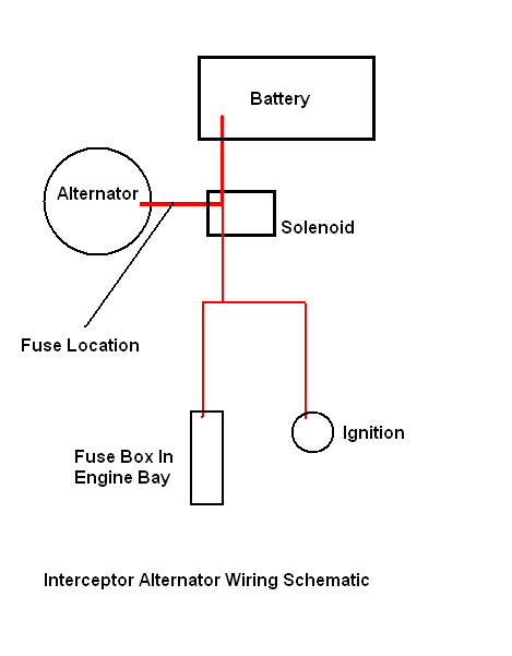
The other end of this heavy duty cable needs to do two things: it needs to supply current to the ancillaries (i.e. via the loom) and also it needs to charge the battery. It is important that this cable is NOT taken direct to the battery +ve terminal but instead goes to where it can connect into the existing loom. On Int MkIII (and probably others but don't quote me) the right place is the input side of the heavy duty connector at the starter solenoid (underneath the battery tray). This is where the original Jensen alternator output wire went to and where several loom wires are also attached. The cable up to the +ve battery terminal also originates here. It's important that the alternator output cable goes to this junction, rather than direct to the battery.
The old brown wires (3 off, one thick, two medium) that were connected to the old large alternator output terminal need to be connected together (a nut and bolt works ok) and then insulated and taped up out of the way. They need to be connected together because they feed fuse box "A 5/6" and "A 7/8". This only works because the other end of the thick brown wire is still connected at the starter solenoid end (to the new alternator output wire/battery). 2) A 6.3mm male terminal labelled "S" There are two terminals, one labelled "L" and the other "S". The socket of these two terminals is designed to accept a block plug to wire into a Mitsubishi loom. But there's no room for this plug so bin it and use a pair of normal insulated female blade terminals instead. Looking at the rear of the alternator the "L" connector is on the left and the "S" connector is on the right.
The "S" terminal is the sense wire. This is the input to the alternator's internal regulator. It senses (reads) the loom's voltage and controls the alternator's output accordingly. It's important that this wire is not simply a wire from the battery/alternator output. It needs to sense the voltage at the looms "main junction"; this is so that the alternator's regulator is reading an average voltage (with voltage drops throughout the main part of the loom) and can correspondingly raise the alternator's output high enough to get the voltage in the main part of the loom up to about 14.5 volts (exact values vary slightly by alternator type etc.).
So, there's no point connecting the sense wire near the battery/alternator output as that will always give a false (good) voltage and the alternator won't raise the loom's voltage high enough. I don't know where the originating connection is physically as it's buried somewhere inside the loom (you can see where it is logically from the Jensen wiring schematic) but at the alternator end it is a white wire that was the input to the old external regulator. The chances are that you'll have to strip this wire back inside the loom a way so as to get to good non-corroded connection but it's important that it is found and that the wire you add to it (to go to "S" on the alternator) has a very good connection (solder best, scotch locks very bad).
If the loom that this wire is part of is in very bad condition (especially the dash-to-engine bay plug/connectors) then there's a good possibility that the sense wire will be higher resistance than it should be which will tend to make the alternator's output correspondingly a bit higher than it should be (making the above "buffer" long lead even more desirable). This is something you'll have to connect up and try. If the voltage at the battery is very high (15, 16, 17v etc.) then this could be the reason why. If this is the case then you may have to revert to just putting the sense wire to the main connection at the solenoid. This will mean that you're not getting the full benefit of the high alternator output but at least you won't fry your battery (or yourself if the loom melts due to its high resistance bottlenecks). 3) A 6.3mm male terminal labelled "L". This second terminal is for the dash warning light. Connecting the bulb, even if you don't actually put it in the dash (there's no Jensen hole but some people have sacrificed their fuel flap warning light) is still important. The light is wired with switched ignition +12v on one side (doesn't matter which) and the other side to the "L" connector on the alternator. When the alternator is not charging (either 'cos you've not started the engine yet, or due to a fault) then the lamp will have ignition +12 (or whatever) on one side and 0v on the alternator "L" output - so the bulb will light up. When the alternator is producing an output then the "L" will also be live so the bulb will have the same voltage on both sides so will not light up. If your alternator is ever struggling to produce enough output volts (slipping belts, old loom, all accessories on etc.) then there will be a slight difference between the voltage on the battery-side of the bulb and the alternator's side - this will make the bulb glow a bit so it's a good indication of something amiss.
The warning bulb also has another important role. The alternator needs a small amount of current flowing through its field windings in order to start the internal regulator. The current flow through the warning light is enough to achieve this which means the alternator will start producing output as soon as it's spun up by the engine starting. Without the warning bulb there will just about be enough residual magnetism in the iron core to also generate an initial current but not really enough initially at tick-over; you'll have to blip the throttle to raise the revs before the alternator will kick in.
Just a final point to re-emphasise: even if you've done all of the above, it will still be the case that most ancillaries will be fed via the old existing loom so even if you're "sensing" properly and delivering good volts to the main junction then you can still have problems (dim lights etc.) due to the old high resistance loom/connections. If you do make any wiring changes (e.g. relays for your headlights) or add new items (e.g. big cooling fans or electronic ignition) it's important to add all new wires and to terminate them all at the main junction where the big alternator cable is also connected. And finally, finally, always carry a fire extinguisher and good insurance...
|
|
|