|
|
|
Jensen Monday Club |
|
|
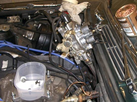
At a day at Santa Pod drag strip we discovered that Steve Payne’s throttle body fuel injected 440 was only about 2.5 seconds faster (standing 1/4 mile) than Chris Miller’s standard 650cfm Holley carburetted car.In theory Steve’s car should be quicker even though the injection vs. carb battle is pretty close at wide open throttle. Steve’s car also ran out of revs before it ran out of track, with a maximum 4,550 RPM, so never got into top gear (change point is 4,600-4,7000 RPM) Various remedies for the “lack of revs" problem were tried, such as valve spring replacement, before it was discovered that the cam had been incorrectly supplied, and was in fact for a motor home! Although this gave tremendous low down torque, it was limiting the engine’s ability to rev. After various “words” with the cam supplier a new “warmer” cam was obtained (Crane 643901 with an advertised duration of 204-215 @ .050 lift). For details of fitting a "roller cam" go here The Preparation Preparation, preparation, preparation… · Make sure you have enough bacon and doughnuts. This is not a low calorie job. · Make sure you have enough coffee (for doughnut dunking) and plenty of beer (to celebrate when you’re done driving, of course). · Make sure you have enough time: it’s do-able in a single (long) day. · If you’re replacing the inlet manifold gasket, you may want to paint the new one’s top side (Jensen black of course) the previous day. · And finally, draining the radiator the night before can save a lot of time… There won’t be mention anywhere in these notes about jacks, axle stands, level ground, blah, blah, blah. All that safety stuff is left to the reader, and no responsibility, liability, blah, blah is accepted. In other words, if you get it wrong, it’s not our fault… Steve’s Throttle-body Fuel Injection and Edelbrock Inlet ManifoldBecause Steve’s car is fuel injected there are several things visible in the pictures that are not part of the cam swap, so if you see something different to standard (usually posh red anodised bits) then these aren’t relevant. Also, the ‘photos show the standard inlet manifold being replaced with an Edelbrock Performer dual-plane aluminium manifold. This isn’t part of the cam swap, it’s just being done at the same time.
The Detailed StepsEat as many doughnuts as you can whilst your hands are still clean ! Use a tie-wrap to hold the bonnet stay in place (Picture 1) – you don’t want that falling on your noggin !
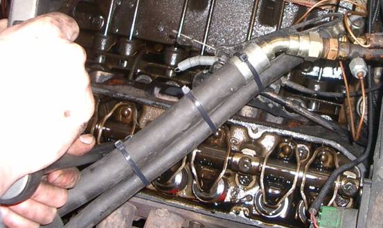
Picture 1: Essential noggin protection ! Disconnect the battery, this step is NOT optional ! Remove the air filter and disconnect the throttle link to the carb. You then have a choice: either remove the carb completely or tie-wrap it up out of the way, but watch out for any petrol spillages from the fuel bowls.
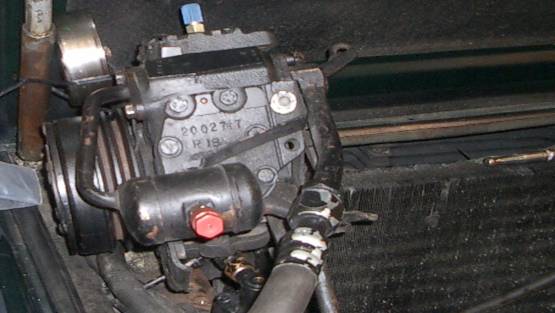
Picture 2 – this is actually Steve’s fuel-injection throttle body not a carb, but you’d worked that out, so no fuel to leak ! Picture 2: “Carb” Partially Removed and Tied Up Clear Disconnect the radiator fans’ power source and remove the complete fans and shroud assembly all as one piece. Disconnect and then remove the radiator (may also need to remove the screen-wash bottle for clearance). Leave the air conditioning condenser in place; it can just be pushed towards the front at the top slightly when needed to allow access to the cam (see Picture 28). Slacken alternator & idle pulley, and unbolt the PAS pump, but leave all hoses connected; just lower it down and leave sitting near the chassis cross-member. Unbolt the alternator, it’s disconnected mechanically but can be left more or less in the same place. You can also leave the electrical connections in place if the wires are long enough, else disconnect and remove whole thing.
Picture 3: Note the relative position of alternator bracket spacers – it’s easier than guessing when re-fitting ! This is a non-stock high output alternator (Mitsubishi 95 amp) but the brackets are in the same position. Unbolt the air-con compressor, set aside don’t disconnect ANY hoses; just un-bolt and set aside the pump. It will need to be tie-wrapped in place to stop it falling.
Picture 4: Air con compressor Unbolted and Set Aside Unbolt and remove the idler pulley.
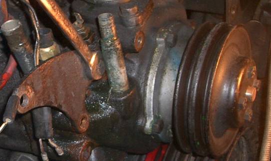
Picture 5: Removing the idler pulley. Having previously disconnected the top and bottom hoses at the radiator end, now disconnect the water temp sender and then un-bolt the water pump housing. One of the bolts needs to be removed as the housing is moved away from the block as there isn’t space to simply remove it with the pump in-situ.
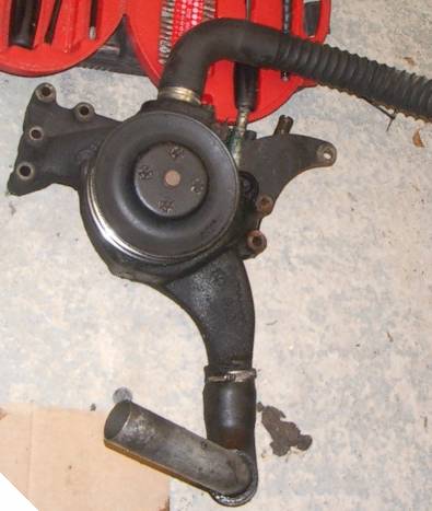
Picture 6: Unbolting the water pump housing. Leave the pump itself and both hoses attached to the housing; this ensures they’re in the same relative alignment when replaced (not vital but saves some time).
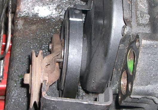
Picture 7: Hoses left attached to the pump housing for easy re-alignment. Remove the crank pulley (small bolts). This is easiest from underneath with a long extension bar.
Picture 8: Easiest way to remove pulley-to-damper bolts. The markings on the pulley and damper are really for Steve’s E.F.I ignition mapping ring (the red bit). The relative position of the pulley set and damper are not important.
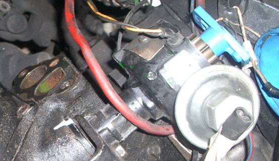
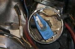
Picture 9: Mark the position of the dizzy body relative to the block. We found “TipEx” (a.k.a “SnoPake” or “Liquid Paper”) typist’s correction fluid to be excellent for this purpose. You can put it on thick and it dries fast, and it doesn’t seem to mind dirty or oily surfaces.
Picture 10: Mark the position of the rotor (engine at TDC).
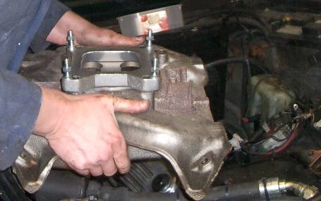
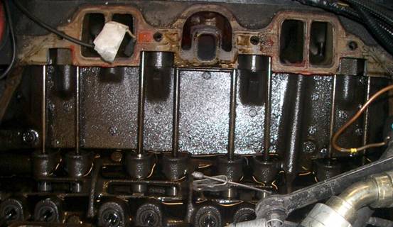
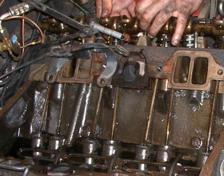
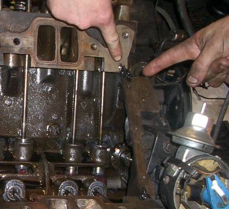
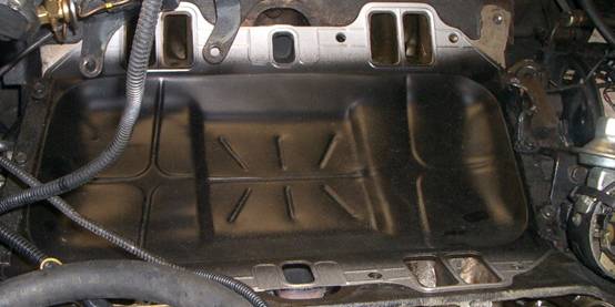
Picture 11: Unbolt and remove the inlet manifold – careful, it’s heavy !
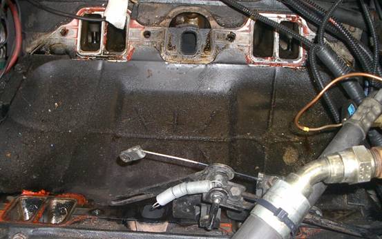
Picture 12: “Valley Pan” gasket seen for the first time. Once the inlet manifold has been removed you can see the valley pan gasket for the first time. The two centre holes are for exhaust gas cross-over through the inlet manifold. This heats the manifold for improved vaporisation, activates the bi-metallic choke (if fitted) and is also where the Exhaust Gas Recirculation (EGR) valve sits (if fitted).
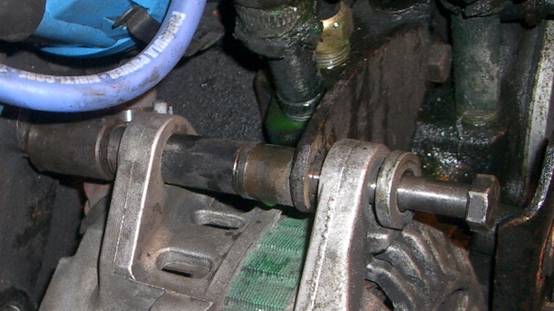
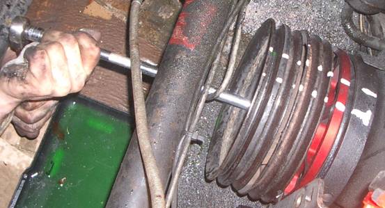
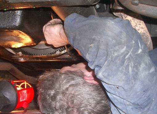
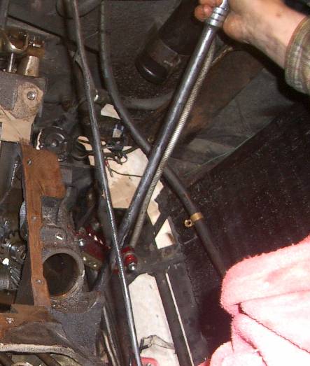
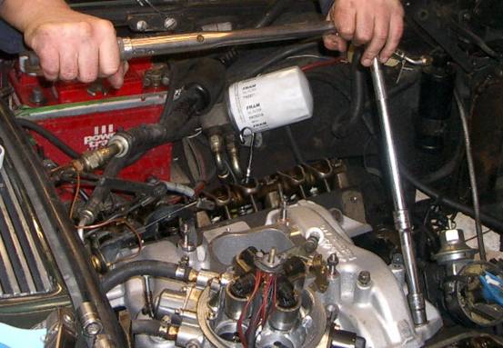
Picture 13: Stopping the crank from turning. To remove the large (1 ¼ inch – 32mm) bolt that secures the harmonic damper to the front of the crankshaft it is necessary to stop the engine turning. The bolt should be tight (135 ft-lbs !) so you can’t do this just by engine compression. You’ll need two people, one can use the breaker bar-socket and the “lucky” one can scrabble around underneath. Removing the semi-circular plate on the lower front of the transmission box will give access to the starter ring; this can be jammed to stop the crank from turning. Once the crank bolt has been removed the Vibration Damper (Harmonic Balancer) can be pulled off the crank. There’s a woodruff key on the crank so you don’t need to mark its position as it only goes on one way. If the damper won’t pull off my hand or gentle “persuasion” with a large bar or screwdriver you’ll need a puller. If you don’t have one then you can use the previously removed idler pulley as a puller; use two of the crank pulley-to-damper bolts to hold the idler pulley onto the damper and then the crank bolt can be unwound to pull the damper of the crank.
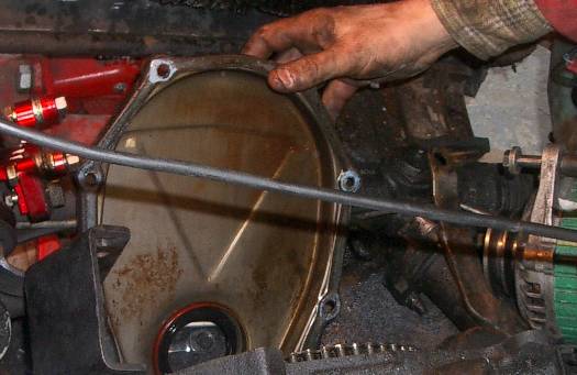
Picture 14: Using the “Idler-pulley-as-a-puller” tool. If you don’t have proper puller to remove the damper you can use the idler pulley as a make-shift puller. Re-insert the big centre crank bolt into the front of the damper but don’t screw it all the way in. Rest the idler against the front face of the bolt (see Picture 15) and screw two of the small pulley-to-damper bolts through the holes in the idler pulley and into the front face of the damper. Screw both in until there’s even pressure on both and then slowly tighten one side then the other to maintain even pressure. You may need to slacken it off and adjust the big centre bolt as the damper is pulled forward. Take care not to over tighten and bend the idler pulley… Remove the Cover-Chain Case. Remove the bolts all around the front face. There are also two bolts which come up through the oil sump front lip and into the bottom edge of the timing chain cover. To remove these jack the front of the engine (with the wheels on the floor not stands) as high as it will go without straining anything. Bend down into the engine bay from above – there should be just enough clearance between the sump and the front cross-member to “feel” a spanner onto the two bolts (an offset-swan-neck spanner is useful to get the bolts started). The timing cover plate can then be lifted away. The front crank oil seal can be seen. Now is a good time to inspect and replace it if it’s worn. It’s an interference fit so simply prize out the old one and gently hammer in the new. If you want to install an “oil slinger” (recommended) you can do so when re-assembling.
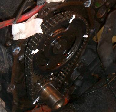
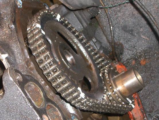
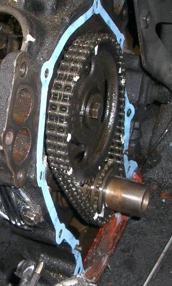
Picture 15: Removing the Timing Chain Cover. Remove the Timing Chain/Sprockets. Mark up the relative position of the timing chain and crank and cam sprockets (see Picture 16) BEFORE sliding them off their shafts (bolts on front face to be removed first).
Picture 16: Marked up timing chain/sprockets
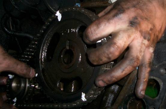
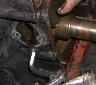
Picture 17: Removing timing chain & both sprockets. Remove the Valley Pan gasket and clean up any old sealant and debris from around the exhaust cross-over passages.
Picture 18: Inlet Manifold Gasket (a.k.a “Valley Pan”) gasket removed.
Picture 19: Removing the cylinder head (a.k.a rocker) covers.
Picture 20: Unbolting the rocker shaft
Picture 21: Clean rocker shaft: dirty hands and T-shirt…
Picture 22: Extracting the push-rods.
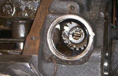
Picture 23: Position of the “dizzy” drive shaft gear marked up with “Liquid Paper”
Picture 24: Extracting the “dizzy” drive shaft/gear.
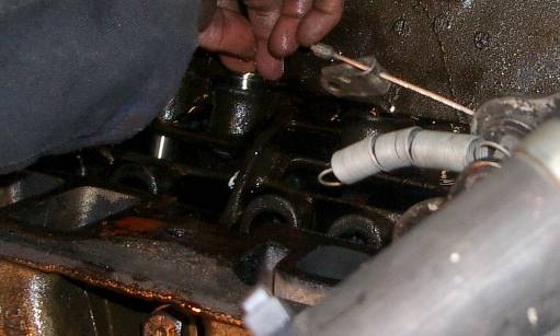
Picture 25: Extracting the cam followers
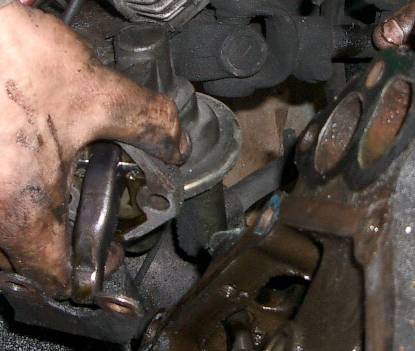
Picture 26: Un-bolt and remove the mechanical fuel pump.
Picture 27: Using an Alan Key to remove the fuel pump drive shaft. Steve’s fuel injected car has an electric fuel pump so the old mechanical one is no longer needed and was therefore removed. A blanking plate is available to cover the redundant hole in the block.
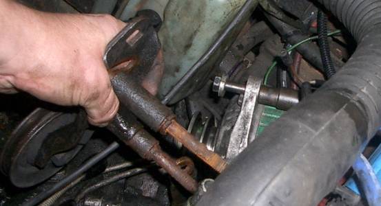
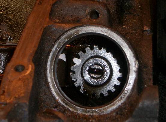
Picture 28: Extracting the cam shaft – at last ! The cam can be pulled out. You may need to push the top of the air-con radiator forward at the top edge to get the right angle.
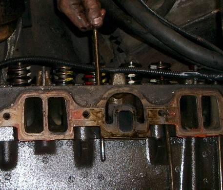
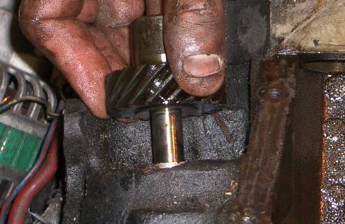
Picture 29: Supporting the rear of the new cam shaft. When inserting the new cam it’s important that it’s supported at the rear end to prevent any damage. You can either use a piece of string looped under the end of the cam or else a thin metal rod bent into a hook shape. The final positioning into the rear can be done by hand.
Picture 30: Strawberry Sauce Sir ? It’s essential that the new cam is provided with lots of lubrication as it won’t get any oil on initial start-up and to ensure it beds in properly. A new cam will usually come with some lubricant but don’t rely on it and get some extra beforehand.
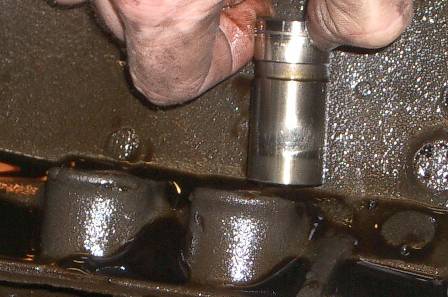
Picture 31: Inserting the new cam followers. The new cam followers simply slide into place, no force needed. Make sure you get them the right way up (note the position of the ring markings on the old ones).
Picture 32: Timing chain/sprockets replaced in original relative position. Slide the two timing cogs complete with chain back onto the cam/crank. Make sure they’re back in the same relative position by keeping the markings aligned. The crank cog has a slot for the crank’s woodruff key so that sets the cog-to-crank alignment.
Picture 33: “Dizzy” drive shaft/gear Re-inserted Reinsert the drive shaft for the dizzy. Use the markings to get it aligned. It twists as it’s inserted so you need to allow for that to get the markings aligned.
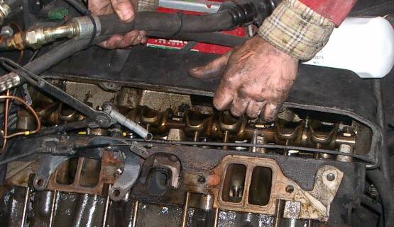
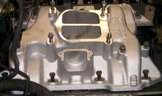
Picture 34: Re-inserting Push-rods & Rocker Shaft. The push-rods are reinserted (they’re not position dependant) and the rocker shaft re-bolted. You’ll need to juggle the position of the push-rods as you tighten down the shaft to ensure the rods seat correctly between the rockers and the followers. It’s easier if one person holds the rods whilst the other positions the rockers. Picture 35: Replace Timing Cover Using New Gaskets. You may need to trim the bottom end of the timing cover gasket (the blue bit above) to get it to fit against the bottom lip/sump gasket. Picture 36: Replace Harmonic Damper & Pulley Set This is reversal of the removal procedure except obviously you don’t use a puller. Just push the damper onto the crank as far as it will go and then use the big front bolt to push it into its final place. This needs to be done up REALLY tight – 135 Ft-Lbs. Bolt the pulley set to the front face of the damper. The next step is to replace the Valley Pan and Inlet Manifold. Picture 37: “Valley Pan” Gasket Sealant (R.T.V Black) Most valley pan gaskets come with installation instructions. The Felpro one we used only recommends sealant in each of the four corners (see Picture 37). However we sealed all around the perimeter. [Addendum: subsequent to the re-build it was found that oil was leaking around the inlet port areas, and also air getting in where the oil was coming out. This gave a variable air-fuel mixture to some cylinders and slightly rough running. The gasket has now been sealed around each inlet port hole as well and now runs much smoother. It may just be the condition of the heads-manifold surfaces but if you use R.T.V (Room Temperature Vulcanising) sealant you need to “wet assemble” to get a good seal before the sealant goes “off”.] Picture 38: The new “Valley Pan” Gasket in Place. Picture 39: Inlet Manifold Ready to be Bolted Down This is an “Edelbrock Performer” inlet manifold. This is a dual plane design to increase airflow at low RPM to give more torque (especially if you put in a hot cam). The part number is 2191. The bi-metallic choke sits in the well on this side – the EGR valve (if you have one) in the hole on the far side – else a blanking plate. Picture 40: Torqueing down the Inlet Manifold Follow the manufactures instructions for the tightening pattern to use for the inlet manifold bolts. The Chrysler workshop manual quotes 45 Ft-Lbs (assumed to be for standard cast manifold-heads). The final steps are now the reversal of the various ancillaries (e.g. air-con compressor). Once these are all in place it’s SHOW TIME ! IMPORTANT: Don’t forget to check the timing and carb settings before starting up. IMPORTANT: You need to “bed in” the cam so FOLLOW THE CAM MANUFACTURERS GUIDELINES NOT OURS ! (we used 20 minutes at 1,500 RPM). You can also check for any oil or water leaks and tighten as necessary. IMPORTANT You will need to change the oil after 100 miles The Parts That We UsedThe following parts were used (excluding any fuel injection-Edelbrock manifold related bits): · Water pump housing to engine block gaskets (2 off) · Inlet manifold gasket (old one can be re-used if in ok state and not damaged when removed, i.e. NO buckles, dents etc. allowed in the port areas. · Timing chain cover gasket · New timing chain/sprockets (only if required) · Crankshaft front oil seal (only if required) · High-temp non-setting sealant, e.g. “Black R.T.V Silicone” (usually comes with a new inlet gasket set) · Gaskets for the cylinder head covers (2 off), old ones can be re-used if they’re ok. · The new cam, obviously. · “Strawberry ice cream sauce” (see text). This may be provided with the new cam but it’s best to use lots and lots so some extra is always handy. · PTFE tape (the stuff plumbers use for water-tight threads) · General water proof jointing compound/leak sealer (e.g. Fernox LS-X) as used by plumbers · large tie-wraps (or strong string would do) · A “special cam positioning tool” (a.k.a a piece of string) · A puller for the harmonic damper (e.g. a bit of steel with 3 holes in it) · Fresh anti-freeze · Fresh radiator water (de-ionised is preferable) Well, that’s about it: relatively easy if you’re methodical, if nothing breaks during disassembly, and if your “mates” don’t eat all the doughnuts…
|
|
|