|
|
|
|
|
|
|
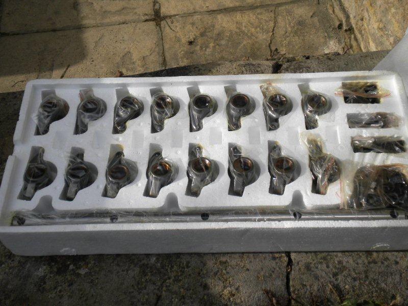
One of the big issues running old cars is that modern oils don't have zinc additives like oils back in the 70s. Zinc is an excellent friction reducer, and was essential for flat tappet camshafts that our cars came with originally. Without zinc, cams wear prematurely, and even if you fit a new flat tappet cam, you run the risk of it being wiped out during breakin even if you use a zinc additive As technology, especially computer assisted design technology, has progressed, then parts are now available for our cars that engineers could only have dreamed of years gone by. As my flat tappet cam waqs showing signs of wear, swithing to a low friction roller cam seemed the best way to go. One of the major areas of engine design that have moved on is valve train components. In fairness our Chrysler engines were massed produced (around 3 million 383's and a million 440's), and used for a huge variety of vehicles, so high tech wasn't at the top of the list of requirements, but as I was due a new cam it seemed a good time to make use of this top notch kit. My engine was in good order generally, but the heads were starting to get a little tired (oil seals leaking, etc) so I sourced a set of 906 heads with, and new valves, from Outrageously Vintage. The service from these guys was 1st rate, and the quality of the work excellent. Sadly, it seems like they are no longer in business and web searches aren't finding any results. I then bought a set of roller rockers, and a set of hydraulic roller followers. The benefits of roller followers and rockers is greatly reduced friction in the engine, which helps with engine cooling, and allows the use of roller cams, which have radically different profiles to flat tappet cams as they have much lower friction levels.
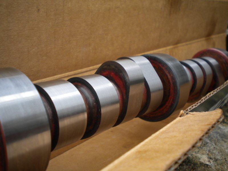
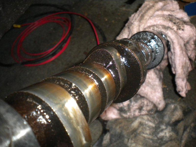
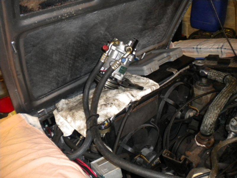
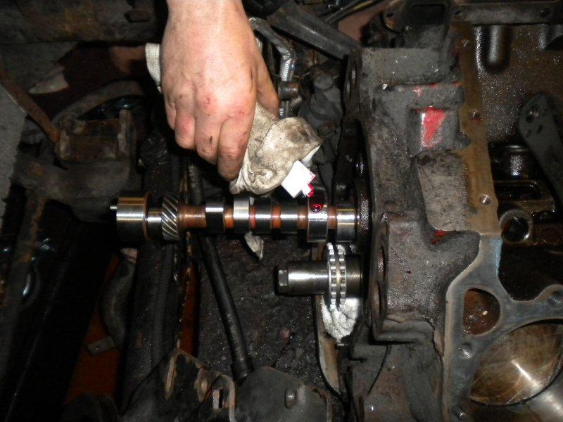
All that was left to find was a suitable roller cam. I had been looking for a while but the cams all seem to fall into either "Tug Boat" or "Racing" categories. They were either for motor homes and all low end torque, or race tracks and top end BHP. I wanted something that would produce good torque but have a little bit of top end bite. Eventually I came across Doug Herbert cams. Herbert pioneered roller lifters many years ago, so I assumed they would know a bit about the things, and they did a cam with a range of 1000 to 6000 RPM (part No CD6P), which would give me the torque and BHP range similar to the factory cam. A lobe separation angle of 112 degrees would also make is very streetable. The cam was roughly the same duration as the standard Mopar cam in our in our engines, so no nasty idle or lack of vacuum issues. Mopar Cam Spec: Herbert Cam Spec: LSA 115 LSA 112 Duration @ .50 228/241 @ .50 220/240 Lift in.450/exh.458 in.485/exh.500 We have a more comprehensive article of a cam change from when we did Steve Payne's car, so this article is geared more towards fitting a roller cam. Top air con tip: Make your pipes long enough so it can be rested on the radiator or wings so you don't have to let the gas out.
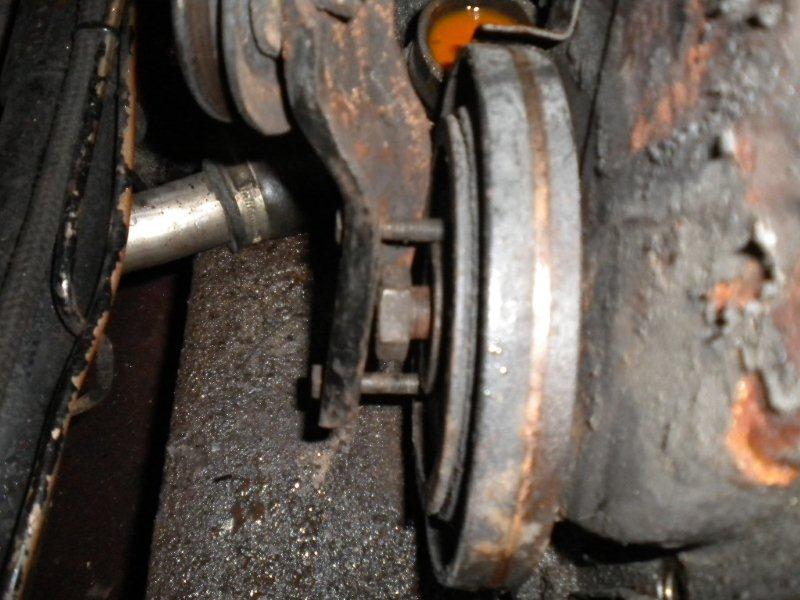
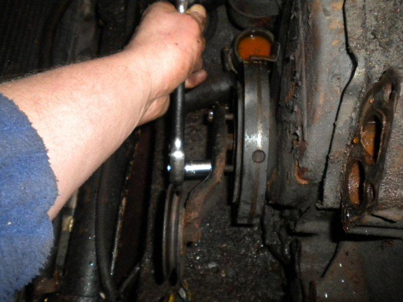
Top harmonic balancer removal tip: Use your belt tensioner pulley
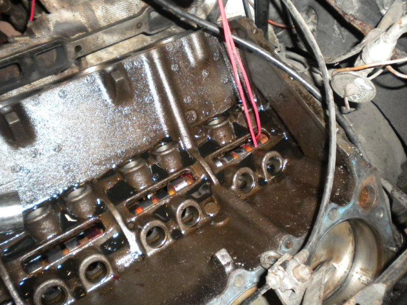
I used a magnetic pick up to remove the old lifters.
Top Cam Fitting Tips:
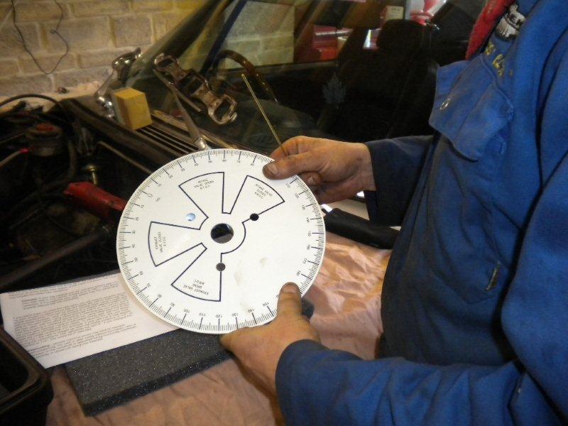
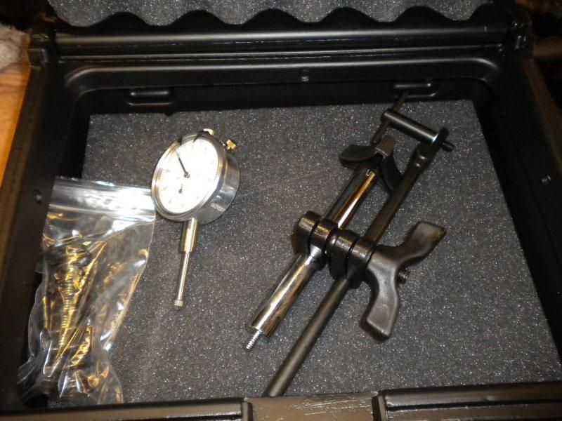
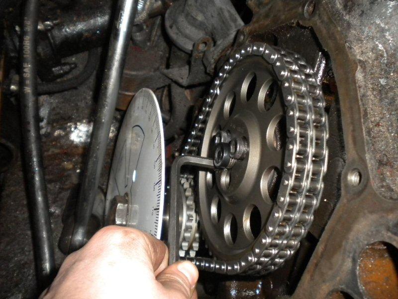
Too make sure the cam was installed as per the specification I had bought a degree wheel and dial test indicator kit.
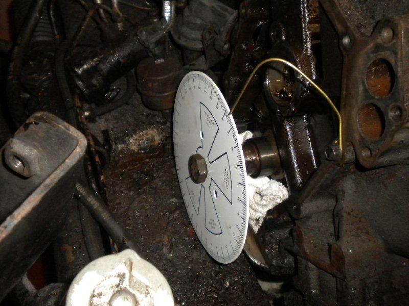
Fitted on the engine
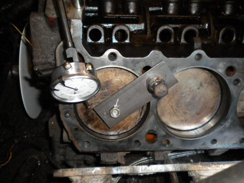
This would enable us to take accurate measurements and find TDC (Top Dead Centre), and the centreline of the cam. To do this you need to make a piston stop.
The procedure is to rotate the engine until the piston touches the stop. The degree wheel is then set to 0 degrees. The engine is them rotated the opposite direction until the piston touches the stop again. The number of degrees rotated is noted (72 in my case) and halved (36 degrees). The engine then rotated to 36 degrees (which will give the true TDC position), and the degree wheel set to 0. This can then be used degree in the cam. To do this you put the DTI (dial test indicator) on the inlet lifter of No 1 cylinder and rotate the engine until it just starts to lift and take a degree reading. You then rotate the engine in the opposite direction until the lifter starts to move again and take a 2nd degree reading.
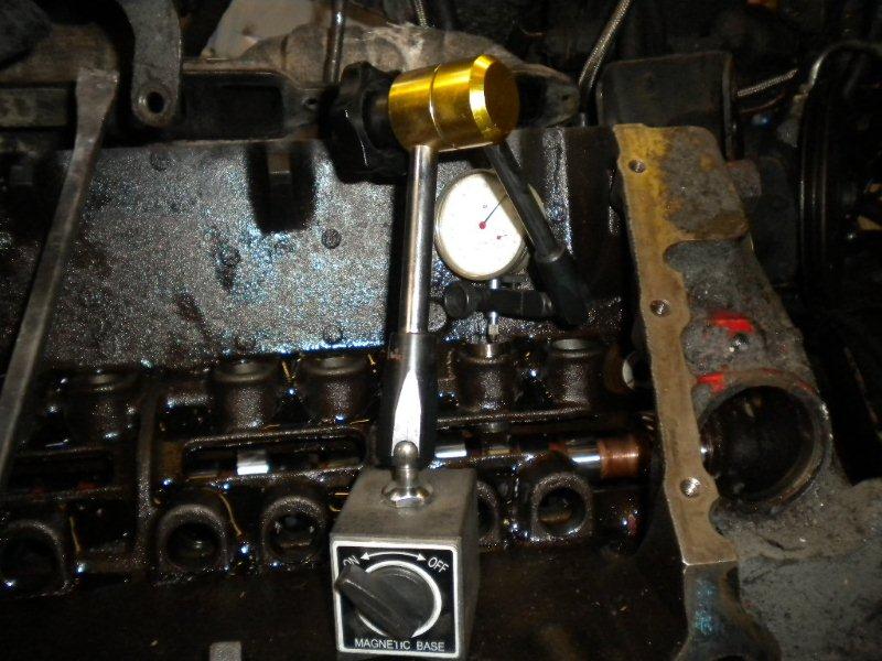
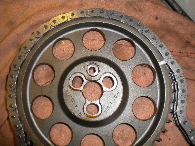
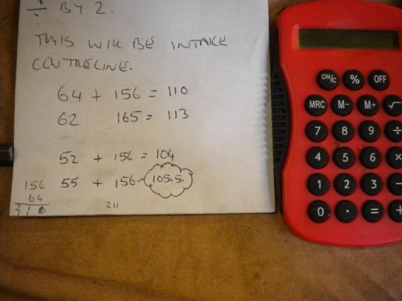
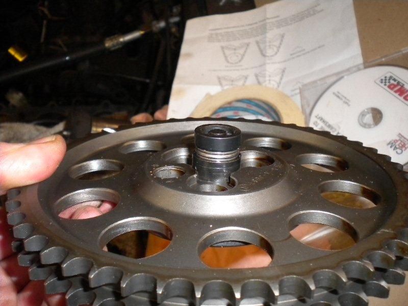
You then add the 2 numbers together and then halve the number. In my case it was 64 + 156 = 220, divide by 2 = 110 degrees. The cam centreline was 106 degrees, so the cam was retarded 4 degrees. That would improve top end BHP, but loose low down torque, so the cam needed to be advanced 4 degrees to bring it back to standard. This shows the value of using the correct equipment and not relying on the cam chain marks. To make adjusting the cam easier I have bought a Cloyes "Hex-A-Just" adjustable cam gear. This has a built in cam that can be adjusted with an Allen key to advance and retard the cam in situ rather than the older degree bushing method.
A quick adjustment of the Hex-a-Just and the cam centreline could be checked again.
After a few attempts I got the cam to 105.5 degrees. The spec was 106, but what's 1/2 a degree between friends.
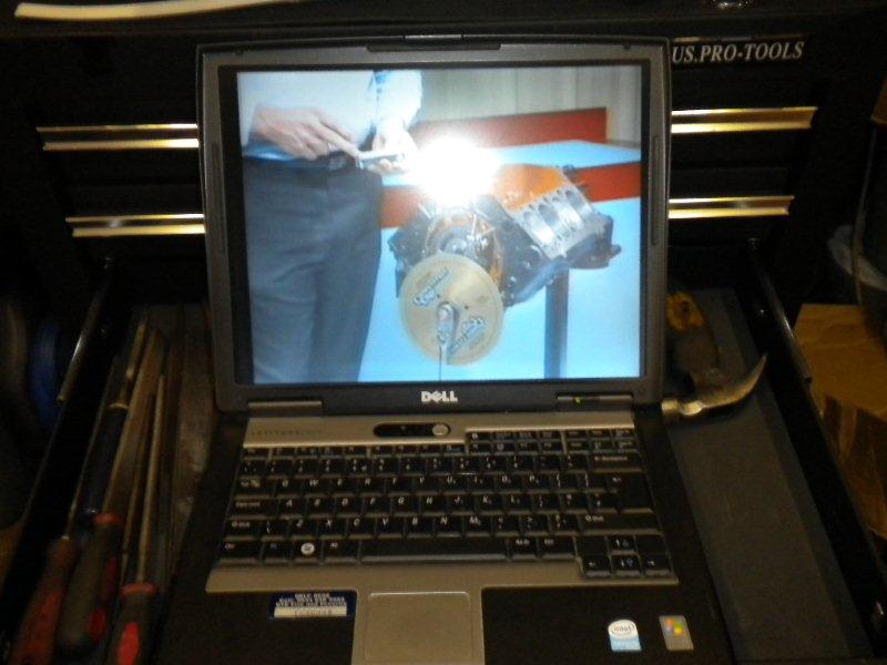
In case you think I'm some sort of engine God, I used a Comp Cams DVD and my laptop to play it so I had a clue as to what I was doing :0)
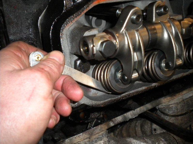
Normal hydraulic cams and followers prevent any movement of the cam in the block, but roller cams and followers don't do this so you have to use a "Cam Button". This sits in the cam chain pulley and touches against the timing chain cover to stop any "Cam walk".
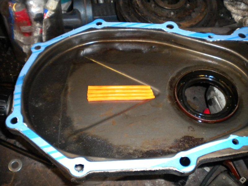
It has to be set to .005 to .008 thou gap. This involved the old engine builders favourite, Plasticine.
It was stuck to the inside of the timing chain cover, and measurements taken from the imprint of the cam button. The button is an "interference" fit in the pulley, and can be knocked in or out to suit. Final adjustment is made by bending the timing chain cover.
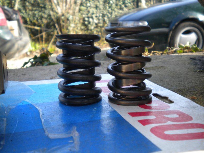
All cams require valve springs matched to the cam you are using, so I had bought a set of Herbert springs matched to my cam. These turned you to be triple springs rather than the standard double. Make sure you use the correct spring for your cam.
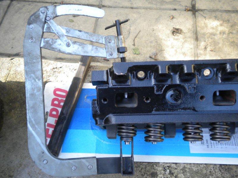
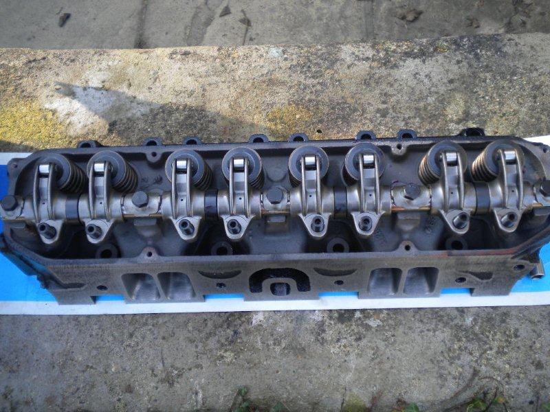
There were then fitted to the heads.
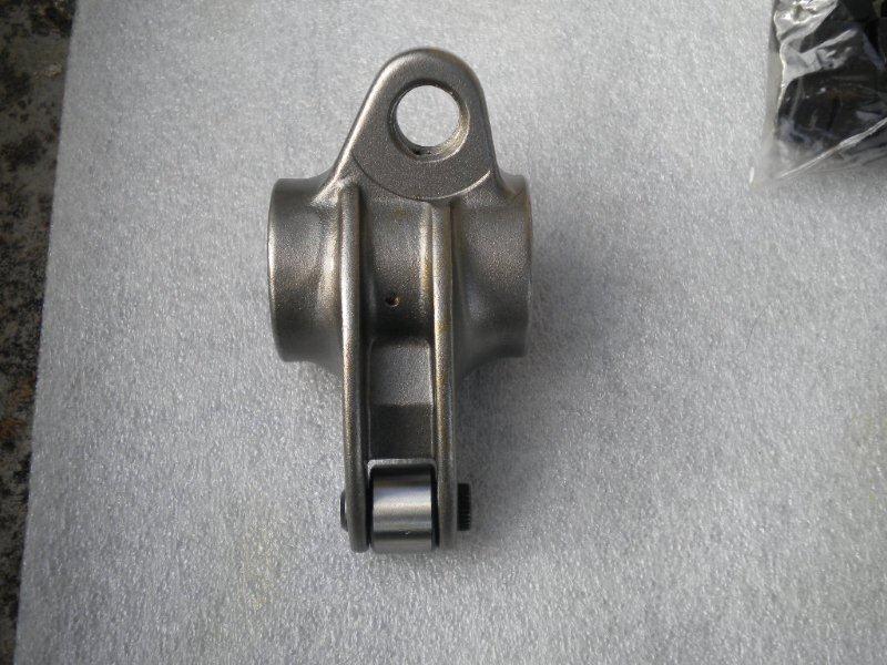
The roller rockers could then be assembled.
Fitted to the head.
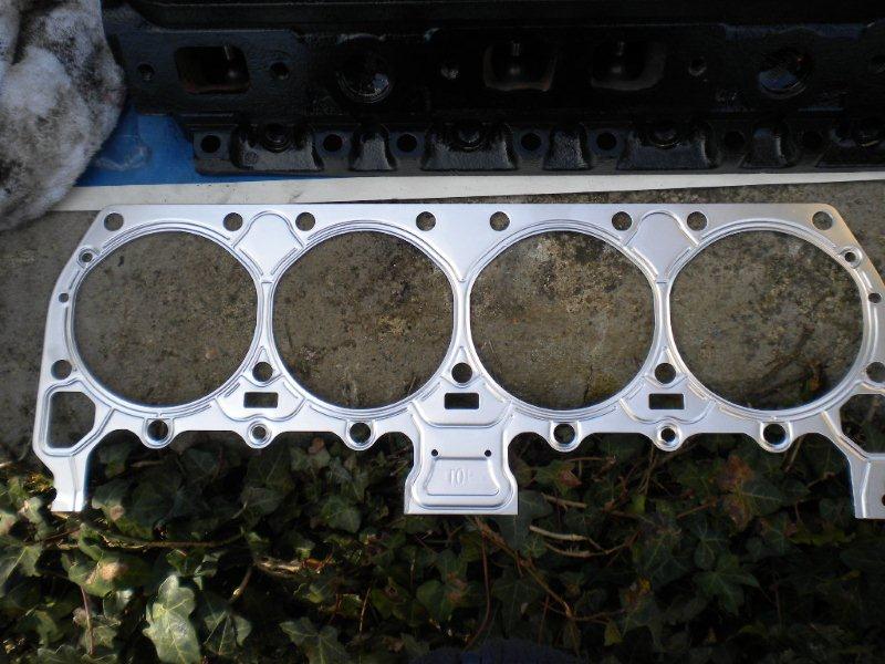
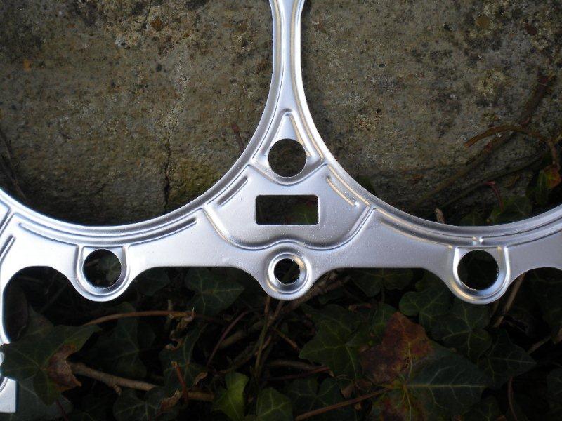
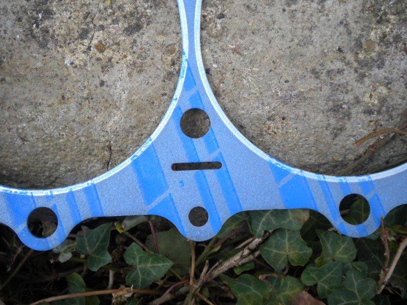
A quick note on head gaskets. I had bought 2 sets, a steel shim .020 thou thick set, and a more usual .040 thou set (this was to allow a bit of extra compression if there was enough valve clearance).
The steel set had the original Mopar sized water cooling slots, but the newer type had the smaller slots that can cause over heating problems on engines which are clogged up with lime scale. The smaller slot gaskets are generally the only ones available as they meet emission regulations. I got the steel shim gaskets from E-Bay.
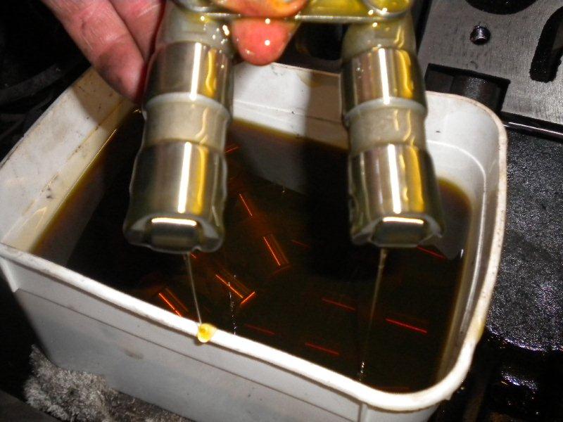
Next job was to install the roller lifers, which had been soaked in engine oil over night to fill them up.
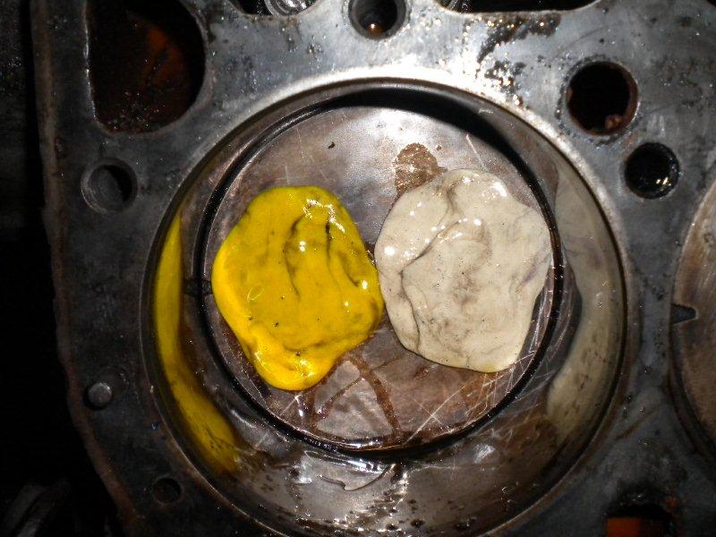
Since doing my car and others, I now question the soaking the lifters in oil. It is recommended by the manufacturers, but I have found it can cause problems with adjusting the preload correctly. The reason seems to be that some fill fully, and act almost like a "solid" lifter. Others only part fill, and other don't fill at all. When you are setting the preload, these differences in the pressure in the lifter can cause issues. As part of "good practice" the engine should be turned over without the spark plugs fitted, or better still, the distributor removed and the oil pump primed with a priming tool. This will fill the lifters under low load, making the need to soak them unnecessary. I next needed to check the valve to piston clearance, and once again Plasticine came to the rescue.
A head was fitted with an old gasket and the valve train and pushrods set up so the engine could be rotated with the valves opening as in normal operation. This was done very slowly in case any valve to piston contact was going to happen. There needs to be a minimum of .080 thou inlet, and .100 thou exhaust clearance. I rotated the engine 2 full revolutions, and then removed the head. There was more than enough valve to piston clearance to allow the steel shim gasket even with the higher than expected cam lift and 1.6 rockers. It was also time to check for coil bind, which is when the springs are compressed too tightly and can lead to them breaking. There needs to be a minimum of .040 though gap between coils to prevent coil bind. In my case these was well in excess of this.
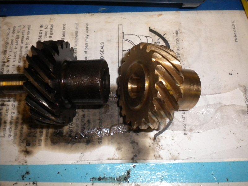
Roller cams are made from billet steel not cast iron, so need to use a bronze drive gear rather than cast iron. Using a billet cam on an iron drive gear will result in failure of the gear. This required a trip to a machine shop with a 50 ton press to swap the gear onto the oil pump shaft.
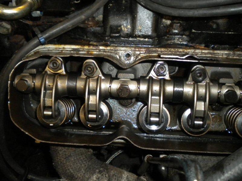
Once the bronze gear was installed, it was a case of putting the engine back together, and setting the roller followers. We used an old rocker cover with the top cut off and plenty of rags as the oil squirts out of the small holes in the top of the rockers when running. This normally hits the baffles inside the rocker covers and drips onto the tops of the valves and rocker for lubrication.
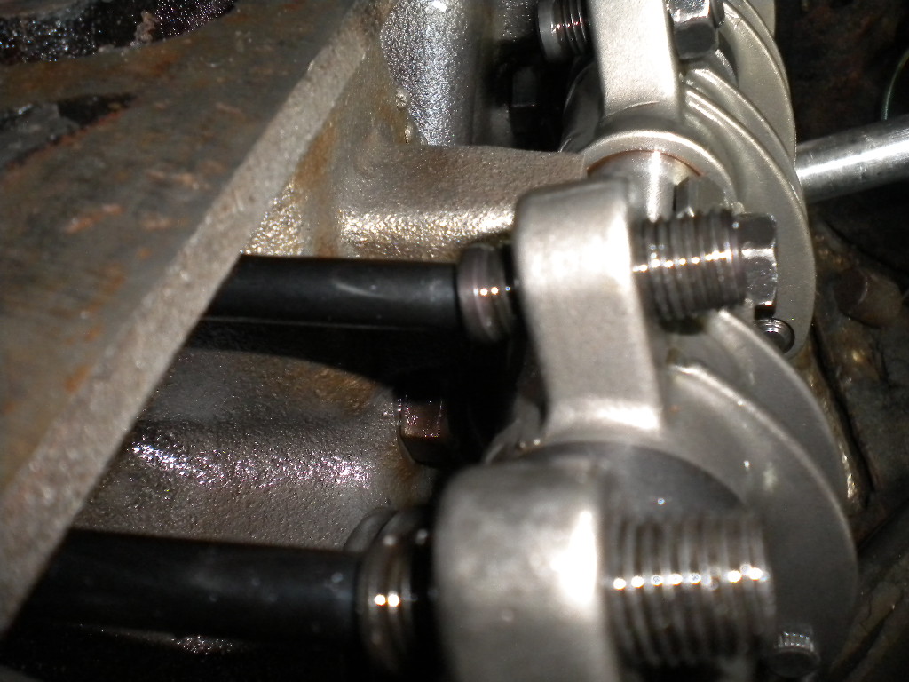
The method we used was to turn the engine until both the valves were closed. The manufacturers recommended method of adjustment is to adjust the rocker till you feel the "squish" in the hydraulic follower. This is called "zero lash" (no slack in the adjustment), and the preload is added from there. This relates back to my earlier comments about soaking the followers in oil overnight. Some fill, some part fill, and some don't fill at all, so the "feel" of each lifter will have different feeling of squish, so you will have differing adjustments across the valves. From experience, the method I use now is to "spin" the push rod between your fingers, and adjust the rocker until you feel contact with the lifter. This gets past the issue of some lifters having different pressures, so you get a more accurate zero lash, and therefore preload adjustment. These are the experiences I have had, but please follow the instruction that come with yours if you are not sure. The next issue I have found is that all the manufacturers call for finding zero lash, then add half a turn of the rocker arm adjuster. This caused all sorts of issues with the pushrods falling out of the rocker arm if the engine oil had bled down, and so there was no pressure in the lifter to keep it in place. This goes back to the soaking the lifters in oil and getting different "squish" feel when using the manufacturers adjustment suggestions. The other issue is the manufacturers call for .50 thou of preload on the lifter. During the time I was having with the roller cam, I checked the pitch of the thread on the rocker adjuster. Half a turn equals .30 thou, so not enough preload. Add to this different "squish" feel from pre-soaking the lifters in oil, it was a recipe for the troubles I had. I now use 1 to 1-1/4 turns of adjustment as this, and the "spinning" the pushrod method have sorted the issues I was having. You may find when you put your rocker covers back on you get a noise as the roller rockers can hit the baffles in the rocker cover. This will involve looking for the marks on the baffle where contact is made, and then drilling holes for clearance in the baffles. It will then be a case of doing a 100 miles or so to let everything bed in, then re-adjust any noisy rockers. Driving impression are of an engine that seems very keen to rev, and with a much more "linear" power curve than before. I have not yet used full throttle until the final rocker setting is done, but the car feels very lively. Some more ignition and carburettor tuning will then be required to get the best set up, but so far it feels like a job well done. * Update One of the jobs I could not do at the time was check for the correct pushrod length. I did the job at Steve Payne's place as he has all sorts of engineering shops and suppliers near him, where I have non. One of the problems with that was I needed to get the car out of his garage and home as he had building works going on, so I had to guess at the pushrod length, then check afterwards. As a quick rule of thumb, 383 pushrods will "get you home" but are not the correct length for long term use. I bought a cheap set of second hand 383 rods for the job. To check the correct length I bought an adjustable push rod.
This allows you to adjust the length until you get the length right. If the push rod is too short or too long it will mean the adjuster will either be too low or high. The adjustable pushrod was set so that the adjuster was about 50/50 above and below the rocker arm. Note that the locknut is removed in this picture. With the locknut in place there is less of the thread above the rocker arm (you can see the arm behind has the locknut in place and can see how little thread is protruding through)
The Mopar system has the rockers on a fixed rocker shaft, which means the geometry is set, unlike the Ford and Chevvy systems which have the rockers on studs. There need to have the pushrod length set very accurately or the geometry will be out. To check the all was ok I cleaned the oil of the valve stem and the roller, and marked the valve stem with marker pen.
I then adjusted the pushrod, set the valve lash and did a full rotation of the engine. I then took the pushrod out which allows you to flip the rocker over to view the stem. I then checked the marks on the stem were on the centre line of the valve (the roller should get no closer than 30 thou to the top or bottom of the stem)
Once you have the correct length, you need to accurately measure the adjustable rod (I will take mine to an engineering shop as I don't have a calliper big enough), then order the correct length and install. The project has not been without it's issues. See here for details
|
|
|
|
|


.jpg)
.jpg)
.jpg)
.jpg)