|
|
||||||||||||||||||||||||||||||||||||||||||||||||||||||||||||||||||||

Home Jensen Monday Club |
||||||||||||||||||||||||||||||||||||||||||||||||||||||||||||||||||||
|
|
||||||||||||||||||||||||||||||||||||||||||||||||||||||||||||||||||||
|
The
last major project on 136-8779 was the engine build. There will always be
minor projects to do on a 50 year old car, but all the major items have
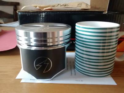
been restored or replaced over the years. Wherever possible, when something has needed changing, improved modern parts have been used, such as polyurethane bushes in the suspension rebuild rather than the original rubber bushes, or a lock up torque converter when the 727 gearbox needed changing. Disclaimer! Any sightings of chrome plated bling parts are purely a figment of your imagination! This isn’t meant to be a detailed engine build guide; there are some excellent books out there that can go into much more detail than I can here (see below). This is more to highlight some issues that may not be covered in a guide book, or in the case of blocks and gaskets, something a bit more Jensen specific. 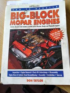 The original low compression 440 engine was in good condition and gave stout performance, but with the refurbished, ported and gas flowed 906 cylinder heads and new roller cam shaft and roller rockers that had been fitted, more compression was needed to get the best out of the new components, and a re-bore with new pistons and all new bearings never hurt anyone. At the same time, it would allow a refurbishment of the engine bay that couldn’t be done with the engine in situ. Me and the Monday Club lads have over the years bought items when they have come up for sale and so we have a collection of parts to keep our cars going. We have a few engine blocks available, so it was a case of choosing the best one for the job. I had previously bought a set of pistons for a ridiculous price off eBay, which were 30thou over size, so it needed to be a block that hadn’t been re-bored before.The pistons I picked up for a song were 6 Pak replacement forged high strength Speed Pro’s, so high quality, high compression, pistons. They also have valve clearance notches, so no issues with valve to piston clearance. 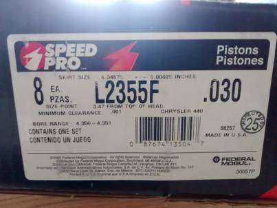 If you have never seen 440 pistons before, here is one next to a coffee mug for scale.
The black covering on the piston skirt is a low friction coating 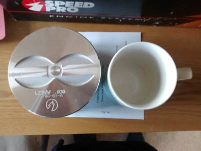 Valve Notches in the top of the pistons
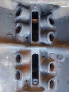
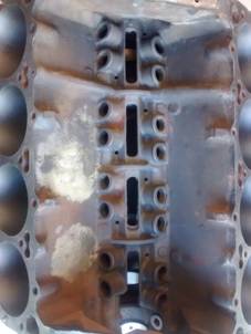
Block Selection A good Mopar website covering blocks and engines http://www.moparts.org/Tech/Archive/motor/36.html Looking at the blocks we had available, one looked like it has standard pistons, so good for a 30thou over bore, and also had the added bonus of the police/heavy duty enlarged “Figure of 8” water passages. 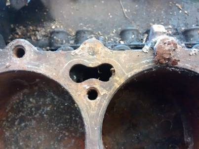
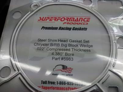
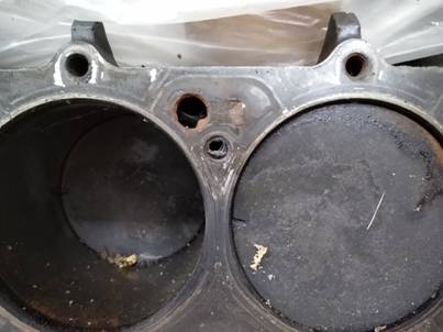 “Figure of 8” Water Passages Standard Circular Water Passages This become important in the type of head gasket used, and the possible effects on cooling, and more importantly, over heating I used steel shim gaskets, the same type as the engines were built with by Mopar. These gave a couple of advantages: 1. Modern gaskets are around twice the thickness (40 thou as opposed to the steel shim gaskets, which are 22 thou), so you lose quite a lot of compression (around 9.5 to 1 instead of 10 to 1) 2. The water passage holes in the steel shim gaskets are the pre emissions sizes. Early gaskets had larger water passage holes to allow good cooling to the heads. In order to try and make old engines pass the new 1970’s emissions laws, Chrysler reduced the compression ratios and also reduced the water passage hole sizes to make the heads run hotter to clean up the combustion. This is a possible cause of the later engines problems with over-heating. Below are pictures of various head gaskets on the “Figure of 8” and Standard water passage holes so you can see the difference. 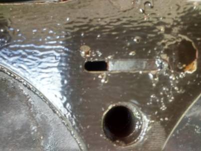 Pic 1 Pic 1Pic 1. Modern small water passage gasket over standard water passage in the block 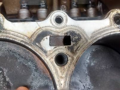 Pic 2 Pic 2Pic 2. Steel shim gasket with large water passage over standard water passage 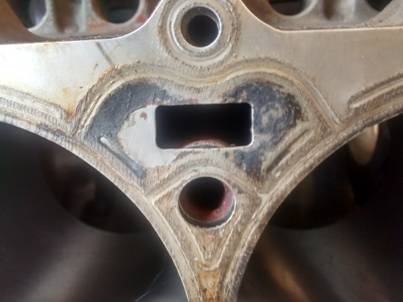 Pic 3 Pic 3Pic 3. Steel shim large water passage gasket over Figure of 8 water passage in the block As you can see in Pic 1, a modern small water passage gasket over a standard water passage block creates a huge restriction to water flow. All the low compression 440’s and probably the later low compression 383’s will be like Pic 1. Early high compression engines (including to 440 6 Pak) will have had the large water passage gaskets but Standard small water passage blocks like Pic 2. The block I chose is described as a Police/Heavy Duty block, so has the larger Figure of 8 water passages. This with the large slot in the steel shim gasket will give the maximum water flow for cooling. Pic 3. One last picture (Pic 4) to show the problem. This is a shot of the old block with the standard holes and a large gasket hole, and you can see even though the engine always had distilled water and anti freeze with corrosion inhibitors, the cooling hole was almost blocked by sediment. 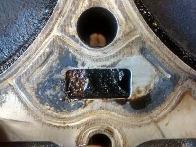 Pic 4 Pic 4It isn’t easy to find these steel shim gaskets, and they are quite pricy, but as you can see, even on a block with standard water cooling passages, make a big difference. Virtually all gaskets you will see for sale will be 40 thou or thicker, and have small water passages, so check before purchasing if you are replacing head gaskets, especially if you have original gaskets in previously un-restored early engines.
Old Block The block had been outside at some point in its life with no cylinder heads fitted, so water had sat in the cylinders,
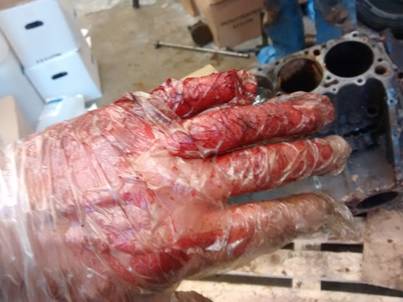
In the process of getting the old seized up pistons out of the block, I almost cost myself a little finger. It still doesn’t work properly now…
Block Modifications Once I had the block home and cleaned up a bit, I could make some modifications the company who made produced cylinders heads had suggested. They raced Mopar’s, so this was a modification they do to all their engines to improve oiling. One of the problems is a lot of oil gets trapped in the valley of the “V” and never makes it back to the sump.
To cure this they recommend drilling 5/16” holes in the webs at the locations shown, so oil can return to the sump
They also suggested drilling the windage tray, which I had done on a previous occasion to these specifications.
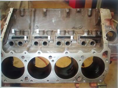
Block Machining The block was now sent off to the machine shop for a hot tank clean, re-boring and new cam bearings. The crank that was in this block was checked at the machine shop, and was found to be in excellent condition, so other than a micro polish it was pressed back into action. As this was a street engine, a cast crank (good for 600bhp) was no problem, and as the existing lock up torque converter was balanced for a cask crank, so it would be a straight swap from the old engine.
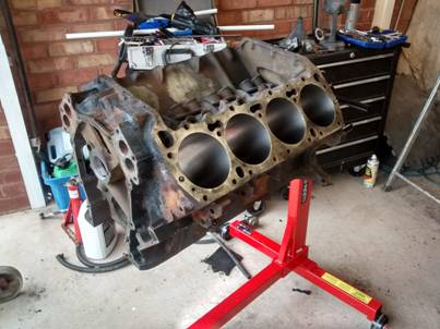
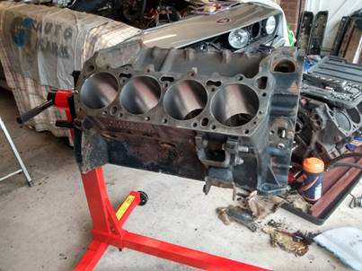
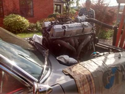
Back with fresh bores and new cam bearings http://store.440source.com/USA-Made-Cam-Bearings-Set-of-5/productinfo/108-1017/ The bores were liberally doses with WD40 to keep rust at bay. It was summer, so dry, but you can’t be too careful. At night the whole thing was wrapped in a large dust bin liner to make sure no moisture got into it. 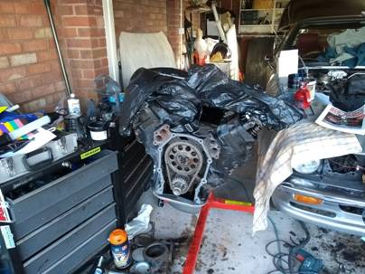 Old Engine Removal So, it was now time to oik the old engine out of the car. Bitter sweet time as it was out with the old and in with the new, but the old engine had served me so well in the 16 or so years I had owned the car. It had only failed to start once, and that was when the original factory starter motor finally gave up the ghost. The old engine had got me up the Prescott Hill Climb, round the track at Castle Coombe racing circuit, down the ¼ mile at Santa Pod drag strip, and got me to the many Monday Club days and days out we had enjoyed. But then the words “Shiny new engine” sprang to mind, so that was that! A warm summers evening was chosen, and Steve and Chris came over to give me a chuck. It’s a pretty straight forward job Taking the engine out, just disconnect all the oil and fuel lines, electrical connections, and all the bolts holding the engine to the gearbox and engine mounts, and voila! A standard engine hoist did the job just fine. It was simply a case of lifting the engine vertically upwards, being careful to avoid hitting anything expensive (Pics 4 & 5) and then pushing the car from underneath it (Pics 6 & 7)
Pic 4 Pic 5
Pic 6 Pic 7 Once it was on the ground all the ancillaries like air con, power steering pump, etc, were removed ready to be painted or refurbished as needed. Items like the heads and cam shaft were then removed as they were all new (less than 1000 miles) so were going back into the new engine.  Engine Preparation New core plugs and pipe plugs were fitted, and the engine painted in POR15 black engine paint. I’m told after nuclear Armageddon that the only things that will survive will be cockroaches and POR15 paint…
http://store.440source.com/Premium-Freeze-Plug-Kit-Stainless-Steel/productinfo/200-1011/ http://store.440source.com/Engine-Block-Pipe-Plug-Kit/productinfo/101-1075/ I also painted the valley of the block in POR15 high temperature engine paint to allow the oil to run back to the sump as quickly as possible. This along with the holes that were drilled will allow the oil to return to the sump.
Important Note! Before getting into the details, I will point out now that all surfaces were thoroughly cleaned before and after each operation, and all parts inspected for damage before use. The manufacturer’s specified lubrication were used during each operation. I say this now for brevity, to save having to keep repeating it at each stage.
Engine Tolerance Checks To add some extra strength to the bottom end, I used high tensile ARP studs. Studs give better clamping characteristics than bolts, so give more strength to the bottom end http://store.440source.com/ARP-Main-Stud-Kit-12pt/productinfo/129-1008/
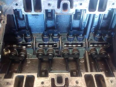
ARP studs fitted along with the new main bearing shells ARP stud installation instructions https://tech.arp-bolts.com/instructions/145-5603.pdf With the bearing shells in place, the crank can be lowered into place.
To check that the main bearing clearances were correct Plastigauge was used to measure all the main bearing and rod bearing journals to ensure they were all within specification http://store.440source.com/Chrysler-H-Series-Rod-Bearings-STD/productinfo/CB-527HND/ http://store.440source.com/H-Series-Main-Bearings-STD-RB-Engine-SMALL-THRUST/productinfo/MS-2233HG/
Plastigauge are precision strips of what appears to be a Red Plasticine type material, which is placed on the crank journal and the bearing cap tightened to specified torque. The bearing cap is then removed and the amount the Plastigauge has spread is measure with the gauge supplied in the kit. This will then indicate if the journals are within tolerances or not. Plastigauge strips on the bearing journals The amount of spread is measured against the gauge Here is a short video on the process All the main and rod journals were within factory tolerances, so the next job was to check the end float of the crank. The No 3 bearing is a “Thrust” bearing and handles the end float of the crank. The end float is the amount the crank can move from front to rear in the block. The engine must have end float to deal with the movement caused by the clutch action in manual cars, or the torque converter in automatic cars. The thrust bearings are the copper coloured bearings on the left of the picture Thrust bearing in the block on No3 journal This was done with the crank in place and all the main bearings fitted and torqued. The end float was measured using a DTI (Dial Test Indicator), and the crank moved backwards and forwards with a large screwdriver. Here is a short video explaining the process. https://www.youtube.com/watch?v=MeiJJAnki4o
A perennial problem with big block Mopar’s is oil leaks from the ream main seal, so I used 440 Source’s aluminium carrier with their Viton seals and silicone end strips. Supposed to be the end to leaks. We’ll see…
Note the slight protrusion at one end of the seal. You do this at opposite ends on the top and bottom seal so that the join is inside the seal carriers and not where the seal carriers join. This is also meant to help prevent leaks. Use plenty of assembly lube on these seals as running them dry on first start will wear them out very quickly. http://store.440source.com/Rear-Main-Seal-Cap-Billet-Aluminum/productinfo/200-1031/ http://store.440source.com/Rear-Seal-Cap-Bolts-Set-of-2-New/productinfo/109-1501/ http://store.440source.com/Viton-Rear-Seal/productinfo/144-1000/ http://store.440source.com/Silicone-Rear-Seal-End-Strips-Kit/productinfo/144-1001/ The end float was in specification, so the whole bottom end could now be fully installed and torqued down using lashings of assembly lube on the bearings, and the ARP supplied stud lube to ensure correct torque settings. I rotated the crank to make sure it turned smoothly, with no tight spots or binding, and it was super smooth. I tried to measure how much torque was required to turn the crank, but just the weight of the tiny 3/8 torque wrench was enough to rotate the crank, indicating all was well.
The connecting rods had been bought from 440 Source, and were high strength Hemi style rods with super strong bolts, so helping to increase the bottom end strength of the engine. Given the forces acting on con rods, I didn’t want to take a chance on old rods, and these were high quality and reasonably priced.  http://store.440source.com/Connecting-Rods-RB-with-Capscrew-bolts-Set-of-8/productinfo/200-1132/ The gudgeon pins (wrist pins) are press fit, so the machine shop did these for me. At the same time he weighed all the new con rods and pistons and matched them so they all weighed as close as possible to each other. Each con rod was numbered with a marker pen to indicate which cylinder it was meant for. The piston as a direction arrow on the top to indicate that it is to point to the front of the engine.
Each cylinder bore was thoroughly cleaned with brake cleaner multiple times. Even if it appears to be clean, do it one more time as the cylinder walls will be covered in the fine grit for the boring and honing process, and this will cause accelerated wear as it will act as an abrasive paste. The piston rings were fitted as per the manufacturers specifications, and staggered at 1/3 intervals around the piston (the end gaps of the rings were set 120 degrees apart so they didn’t line up). The rings were non file fit, but the gaps were checked just to be sure. A short video of the process https://www.youtube.com/watch?v=hcEiZ8Zqfv8  https://www.summitracing.com/int/parts/slp-e-424k30/make/chrysler https://static.summitracing.com/global/images/instructions/slp-wr-9902-30.pdf A piston ring compressor and plenty of oil were used to fit the pistons into the bores.  Care has to be taken not to scratch or score the bore or the crank journal with the con rod or bolts. It is a good idea to use either insulation tape or a plastic sleeve of some sort over the con rod bolts to prevent causing damage.
https://www.tooldiscounter.com/product/goodson-rod-bolt-protectors-set-of-16-gdsrbp-16 Once in and torqued to spec, I used a torque wrench to turn the engine, and with all 8 pistons installed it turned very smoothly at just over 20lbs/ft, so all looking good. The next step was fitting the cam. I did a detailed cam install and roller follower/rocker set up previously, so see that article here. It annoyed me that I only managed to the cam set to 105.5 degrees before, and not the 106 degrees in the spec, so I tried harder this time!
There was around 6 degrees of “Dwell” at Top Dead Centre. This basically means that there is 6 degrees of crank rotation where the piston does not move up or down, so true TDC occurs at 3 degrees Using the DTI, a larger degree wheel than I could use with the engine in the car, and a Cloyes Hex-Adjust cam gear, I got it to exactly 106 degrees. After this it was just general engine reassembly, using the book I detailed earlier. I took the chance to fit a new distributor bush. The old one was pressed out with some threaded rod, some steel tube slightly smaller than the bush, and nuts and washers.
The cylinder heads were installed with the steel shim gaskets, and torqued to spec with new ARP head bolts. All the ancillaries, water pump, etc, were refitted with new gaskets. All the ancillaries had previously both been cleaned and painted, or like the inlet manifold, and valley pan hold down bars, air filter, etc, powder coated.
.jpg)
.jpg)
Any project I do on the car I replace the bolts with stainless steel versions to prevent corrosion, and on the engine ancillaries I used a stainless engine bolt kit, which looks good, is great quality, and not too expensive. https://a2stainless.co.uk/product/chrysler-big-block-440-mopar-engine-bolts-kit/ Engine Bay You can only refurbish the engine bay whilst the engine is out, so it was time to get on with that. Man, what a job. The old engine bay wasn’t that bad to be fair, or at least it didn’t seem it until the engine was out and you could get a better look…
50 years of oil, grease and dust had built up on the chassis and cross members. This was good as there was no corrosion, but I took rubbish bag after rubbish bag out of the engine bay when I started scrapping and degreasing. It took bottles of degreaser, rolls of paper towels, wire brushes, scrappers, and a lot of elbow grease to get it clean. Top Tip! Use a small set of step ladders to climb over the wing to get in and out of the engine bay, and cover the windscreen and wings to prevent grinding sparks and tools from causing damage All the old Hardura was removed from the tops of the inner wings, and everything was stripped back to bare metal. Once that was done, it was all painted with POR15 engine bay paint
Next up once everything was painted was to fit new closed cell sound insulation to the bulkhead.
Followed by aluminium cloth heat shielding
That was a labour of love… Chassis and cross member, POR15 painted.
The whole of the inner wings were then covered in Hardura (thanks Chris!)
Took the chance to replace the bonnet sound deadening at the same time  Engine Refitting As mentioned previously, I haven’t gone into great depth in this article re building the engine, the various Mopar books can go further than I can here, but once the engine was reassembled, with either new or refurbished parts, then it was time to put it back in the shiny new engine bay. There wasn’t anything strong enough to hang an engine hoist from in my garage, and raising the engine on an engine hoist and moving the car underneath it wasn’t an option as we needed to tilt it to angle it back into the engine bay, so we cut a hole in the garage roof and used a steel pole and wooden beams laid across the roof to take the weight of the hoist and engine.
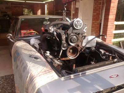
A lifting bracket was bolted to the inlet manifold, and the engine lifted on the hoist
Once the engine was high enough the car was rolled underneath and the engine lower in at an angle to meet up with the gearbox
Bolted in, and carb fitted
Putting the engine back in is relatively straight forward; reconnecting all the pipes, cables, and fittings is another matter. I took the chance to rewrap wiring looms if they looked worn or scruffy, replace hoses, etc. etc. But eventually, it was all back in.
Time to fire it up. Always nerve racking, but not as bad with a roller cam instead of a flat tappet cam as you can’t destroy a roller like a flat tappet on first start up. All went well, and it ran nicely! I had all this left over when I had finished , but it seems to run OK :0)
(Joke, I replaced all those bolts and fittings with new!) I’m about 500 miles in and she has had the first oil and filter change. I’ve recurved the distributor and tuned the carbs to suit the new set up, and it’s very strong. Not used full power or revs yet, but it certainly feels very potent! This is a complete list of 440 Source parts used and the 440 Source parts No’s
For the first time in 21 years of ownership, the engine and gearbox and oil and water tight, with no drips or leaks. That's the kiss of death...
|
||||||||||||||||||||||||||||||||||||||||||||||||||||||||||||||||||||
|
|


 Holes
drilled.
Holes
drilled.


 Honing
grit from the walls of the freshly re-bored cylinders.
Honing
grit from the walls of the freshly re-bored cylinders.


 Old
bush pressed out
Old
bush pressed out New
bush pressed in with dizzy drive gear
New
bush pressed in with dizzy drive gear


.jpg)


.jpg)
.jpg)


